Wheatheart Hydrostatic Portable and Truck-Mount Super Sweep User Manual
Page 18
3. A
SSEMBLY
W
HEATHEART
- H
YDROSTATIC
B
IN
S
WEEP
3.2. H
YDRAULIC
P
UMP
K
IT
I
NSTALLATION
(P
ORTABLE
M
ODEL
)
S
TANDARD
, P
ORTABLE
, T
RUCK
M
OUNT
, & S
UPER
S
WEEP
18
IM1 R3
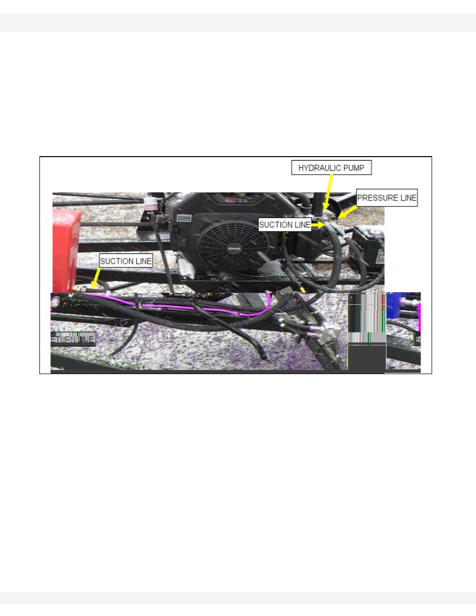
Note:
Hose (12) runs from the “OUT” port on the valve to the pressure (P) side of the
relief valve; hose (13) runs from the relief valve to the pump; hose (14) runs to
return side (T) of the relief valve; and hose (15) runs from the relief valve to the
tank.
I
NSTALLATION
W
ITH
M
OVER
K
IT
Figure 3.8 to Figure 3.10 illustrate the hose assembly process when a mover kit
has already been installed.
Note:
The 24” hose goes from the spool valve to the control valve pressure side (P).
Then, the existing line hooks up to the return line.
Figure 3.8