Menu trees, Lcd programming, Installation ~ lcd programming – ClearOne GT1524 User Manual
Page 12
Installation
~ LCD Programming
8
Technical Services Group ~ 1-800-283-5936 (USA) ~ 1-801-974-3760
5. Use the RS-232 port to connect the GT1524 to a PC (for use with
HyperTerminal), an AP IR Remote Control, or a custom remote control
device.
6. Connect an external amplifier or sound reinforcement system to Line Out.
Use Aux Out to connect recording equipment, such as a VCR. Nominal
output is 0dBu.
7. Using the included connectors, wire a 4-wire transmission system, such as a
video codec, to the 4 Wire/Video Codec In and Out connectors. Nominal
input/output is 0dBu.
8. Connect a local microphone or input from a local sound system or mixer to
Mic/Line In.
9.
Connect the speaker wire to the + (red) and – (black) binding post
connectors.
10. Connect the power cable after making all other connections. As soon as
power is supplied to the unit, the GT1524 initializes and all front-panel
LEDs and the LCD light. The power module accommodates 100–240VAC,
50/60Hz, 22–30W.
For most installations, the default settings in the GT1524 do not need to be changed;
the system can be used as soon as power is applied. However, if you need to
customize any settings, such as telephone connection options or input parameters,
you can do so through the front panel user interface.
The front panel includes a 2x16 character LCD, menu buttons, and LED bar
meter. When power is applied to the GT1524, all LEDs light and the LCD panel
reads INITIALIZING. If initialization is completed without errors, a title screen
appears, showing the product name (top line) and the version number (bottom
line). The title screen remains on display until you initiate some action that writes
information to the LCD panel or the GT1524 detects and displays an error. If an
error is displayed, contact ClearOne Technical Support.
Menu trees
Four main menu trees (menu categories) comprise all of the GT1524 options you can
control through the front panel: Inputs, Outputs, System, and Meters (see Figure
2.4). Enter each of the trees by pressing the up/down buttons and scrolling to the
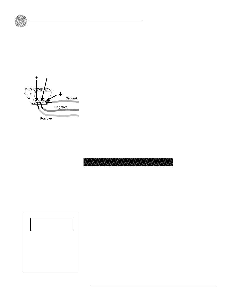
The three terminals in
the Phoenix connector
correspond with the rear-
panel audio contacts (from left to
right): + (positive), – (negative),
and
(ground).
✍
Figure 2.3. Phoenix push-on connector
LCD Programming
Inputs
Outputs
System
Meter
Figure 2.4. Main Menu Trees
ClearOne GT1524
Version x.x