6 connecting cells – Exide Technologies Section 93.10 User Manual
Page 7
When installing cells on the rack, start at the lower step or
tier for stability and safety reasons.
Place cells on the rack so that the positive terminal (marked
“+”) of each cell adjoins the negative terminal (marked “-”) of
the next cell. The standard spacing between cells is 1/2” at
the top of the jars.
Adjacent cells should not touch; nor should any cell contact
the metal rack supports or metal cable conduits. Check for
proper alignment and 1/2” spacing between cells. Adjust
cell position where necessary. This should be completed
before installation of intercell connectors.
Use two 1/2” thick pieces of plywood cut to cell width and 1”
higher than jar height to expedite positioning of cells. Space
cells by placing one piece between the first cell positioned
and the next cell. In positioning the third cell, use the sec-
ond piece of plywood for spacing. The first piece is removed
and used for the next cell placement, etc.
The cell post surfaces have a coating of NO-OX-ID grease
or approved equal applied at the factory. Do not remove any
grease from posts. Re-coat any surfaces that may have
been exposed during handling of cells.
Also closely examine factory coated post contact surfaces
for presence of foreign substances which may have been
introduced through handling or construction activity in the
installation area. If the foregoing is noted, remove the NO-
OX-ID grease or approved equal with paper wipers and
apply a new coating. Also inspect posts for corrosion. If cor-
rosion is found, clean posts with brass suede brush or plas-
tic scouring pad and re-grease.
7.6 Connecting Cells
Refer to the cell arrangement drawing to determine the
quantity, size, and correct positioning of the intercell con-
nectors. On the “N” type cells using 1 1/4” wide connectors,
the bolt holes are located off-center. Position the connector
so that the lesser dimension faces downward on the cell
post.
Gently clean contact surfaces only of the lead plated inter-
cell connectors, terminal plates and cable lugs using a brass
suede brush or 3M Scotch Brite scouring pad. Caution: Do
not use powered wire brush or course abrasives, as lead
plating may be removed exposing copper.
As contact surfaces of posts and connectors are cleaned,
apply a thin coating of NO-OX-ID grease or approved equal
to these surfaces only.
Starting at center of the cell row, install connectors per
wiring diagram and cell arrangement drawing furnished with
the battery.
On cells using stainless steel bolts, washers and nuts, make
sure a washer is placed between the bolt head and connec-
tor as well as between the nut and connector with the rolled
edge against the connector. Never install washers between
the connector and the cell post. (See figure 2A).
As intercell connectors are installed, adjust them to a level
position and finger tighten hardware.
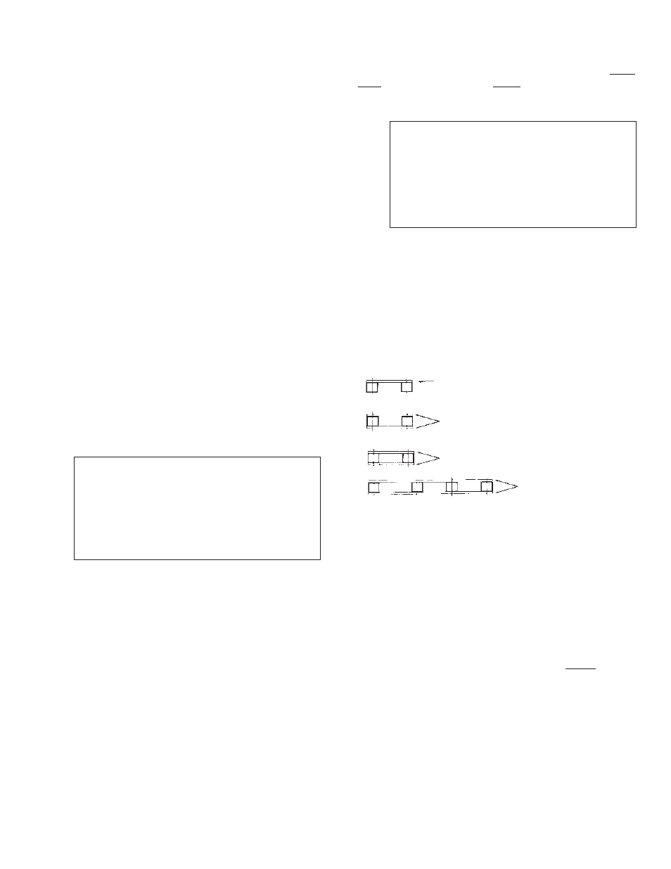
After all connectors are installed, the hardware should be
tightened using insulated tools as outlined in the following
illustration. (Figure 2):
Figure 2
Torque both the bolt head and the nut of stainless steel
hardware to their prescribed torque values. Torquing only
one side of either combination will not provide the desired
tightness.
Re-torque stainless steel hardware 4 to 6 hours after initial
torquing to allow for initial relaxation of connection compo-
nents.
Complete connecting of cells by installing necessary inter-
row, inter-tier or inter-rack cable connectors. Do not connect
battery to charger at this time.
Take and record connection resistances (See Section 19.0)
of cell to cell and cell to terminal (including inter level and
load connections). This is particularly important on high rate
applications. Remake any connection that has a value more
than 10% or 5 u
Ω, whichever is greater.
Re-check to be certain that the cells are connected positive
(+) to negative (-) throughout the battery string. Measure
the total voltage at the battery terminals. The voltage should
be equal to the number of cells times the voltage of one of
the cells. Example: 60 cells times 2.05 volts = 123 volts.
CAUTION!
FAILURE TO OBSERVE ABOVE PROCEDURE
MAY IMPAIR INTEGRITY OF ELECTRICAL
CONNECTION AND CELL PERFORMANCE.
4
CAUTION!
WHEN INSTALLING TERMINAL HARDWARE
DO NOT PERMIT ANY ITEMS TO FALL INTO
CELL. IF SUCH MATERIAL REMAINS IN THE
CELL,
CONTAMINATION
WILL
RESULT,
REQUIRING REPLACEMENT OF THE CELL.
QUANTITY AND THICKNESS
OF INTERCELL CONNECTORS
TORQUE (INCH LBS).
1/8” or 1/4”
(D cells only)
100
1/8”
(M & N cells) 100
1/4” or two 1/8”
(M & N cells)
150
1/4” (PDQ, N & H cells) 150