3 connection resistance measurements – Exide Technologies Section 93.10 User Manual
Page 17
Tests reveal that a reduction in the original torque value of
30% still provides a functional electrical connection if there
is no corrosion between contact surfaces.
Retorquing of connections should always be to the recom-
mended value (See Section 7.7).
19.3 Connection Resistance
Measurements
Connection resistances are very small, usually in microhms.
Therefore, precautions must be observed so that the mea-
sured values are meaningful and not misleading. Different
connector hook-ups require that the measurement tech-
nique allows for these differences.
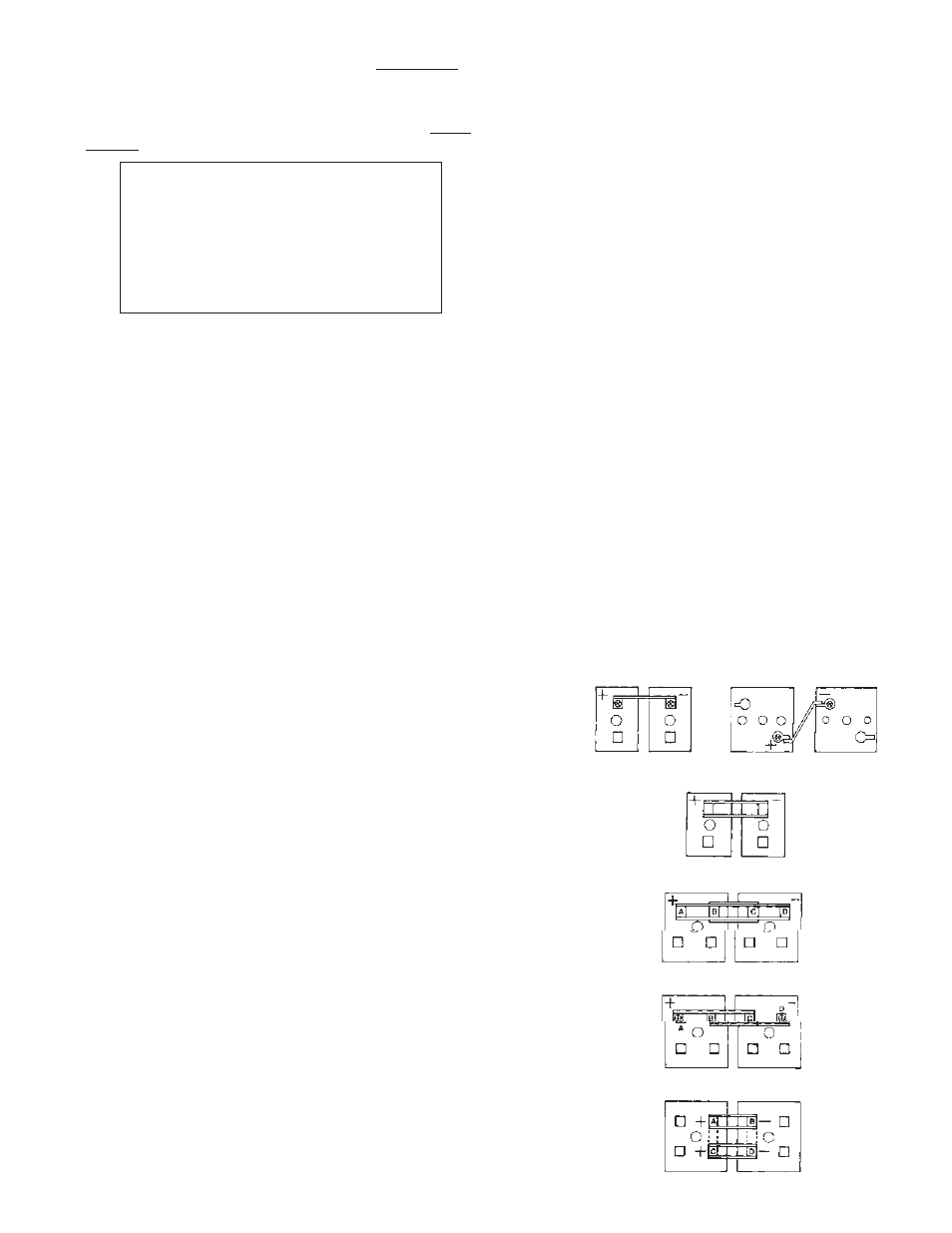
(i)
Single Connector Hook-ups. (Figure 6)
When measuring the resistance of single connec-
tor hook-ups between adjacent cell posts (or in the
case of flag terminals between multi-cell units), the
probe point locations must be at the same location
for each similar type connection. If the probe part
departs from the center point indicated by “X” in
Figure 6, the measured resistance value can vary
due to either an increase or decrease in the lead
mass
included
in
the
measuring
points.
When con-
ducting subsequent monitoring of
connection resis-tance, it is important that the same
probe
point
locations are used so that any measured increase
(or decrease) is a true increase (or decrease) due to
connection degradation and not due to using a dif-
ferent probe point location.
(ii)
Parallel Connector Hook-Ups.
(Figure 7)
Parallel paths exist in this hook-up and measure-
ment of connection resistance include all four con-
nector post interfaces. The location of probe points
is not critical here because of the existence of paral-
lel paths. An increase (decrease) in the lead mass
between post and connector interface on one side is
cancelled by an equal decrease (increase) in the
mass on the opposite side.
(iii) Four Post, Four Connector In-Line Hook-Ups.
(Figure 8)
Cells with four post connector hook ups require two
measurements to monitor all eight post-connector
interfaces. Measurement is made in two steps—
First between points A and C and then between
points B and D. The measured values should be the
same. Values appreciably different (5 micrhoms or
more)
require
reworking
of
connections
as
described in Section 19.0.
(iv)
Four Post, Two Connector Staggered Hook-Ups.
(Figure 9).
Cells with four post staggered connector hook-ups
require two step measurement as described above in
(iii). In addition, the probe point locations for points A
and D (See Figure 9) must be centered as described
above in (i).
(v)
Four Post, Connector Parallel Hook-Ups.
(Figure 10)
Cells arranged end-to-end have parallel current paths
above and below the cell covers and require that resis-
tance measurement make allowance for the same. The
current paths above the cover are provided by the con-
nectors and the path under the cover is provided by the
busbars (shown by dotted lines in Figure 10). Most
resistance meters apply 10 amperes DC to the connec-
tions being monitored. If this was done between posts
A and B in Figure 10, the current will divide through the
busbars between AB and CD and the resistance value
will be about half of the actual value, provided all con-
nections are good. If the process is repeated for posts
C and D and the two resistance values are compared,
the difference, if any, indicates differences in the two
parallel paths as well as poor connections at the post
connector interfaces. A better and preferred technique
is to apply the 10 amperes DC to posts A and D such
that equal current paths are provided. Then, the differ-
ences in readings across AB and CD will reflect con-
nector interface problems in either of the two external
intercell connections. Both intercell connections should
be reworked as described in Section 19.0.
CAUTION!
TOO FREQUENT RETORQUING OF
CONNECTIONS IS NOT RECOMMEND-
ED AS THIS WILL RESULT IN DISTOR-
TION OF CELL POSTS, CONNECTORS,
ETC.,
THUS
DEGRADING
RATHER
THAN IMPROVING THE CONNECTIONS.
14
Figure 6 Single connector hook-ups
Figure 7 Parallel connector hook-ups
Figure 8 Four post, four connector in-line hook-ups
Figure 9 Four post, two connector staggered post hook-ups
Figure 10 Four post, four connector parallel hook-ups