CCI Thermal Technologies G Series - Industrial Infrared Gas Catalytic Heater User Manual
Page 5
5
Separate Installation and Operation Instructions are available for industrial heating applications.
7.0 12V HAZARDOUS
ELECTRICAL INSTALLATIONS
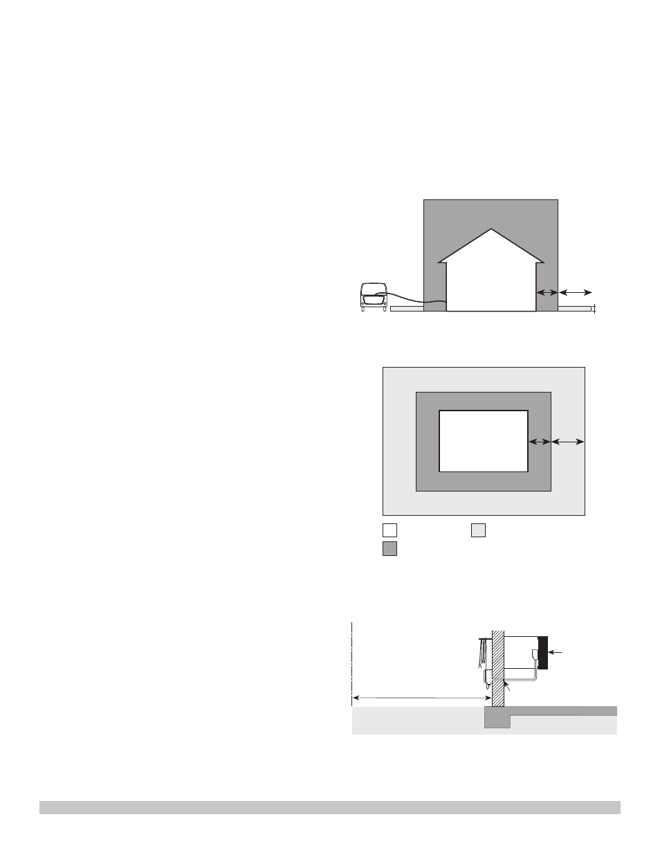
7.1 Most oil and gas production buildings have
an area classification as follows:
(i) Class I, Division 1, within the building.
Refer to FIGURE 7 and FIGURE 8.
(ii) Class I, Division 2, up to 10 ft (3 m) from
the building in any direction. Refer to
FIGURE 7 and FIGURE 8.
(iii) Class I, Division 2, between 10 ft (3 m)
and 25 ft (7.6 m) from the building in all
directions at an elevation of 18” (0.45 m)
above the ground. Refer to FIGURE 7
and FIGURE 8.
(iv) Connection to the power supply must be
outside of the Class I, Division 2 location.
(FIGURE 9). All electrical apparatus and
wiring within this area must conform to
the appropriate codes.
8.0 SPACE HEATING
8.1 A separate heat load calculation should
be done for each building in which a
Cata-Dyne™ heater will be installed for
space heating purposes.
8.2 The heatload calculation determines the building
heat losses through the structure and allows
for air infiltration (visit www.ccithermal.com
for the sample Heat Load Calculation).
8.3 Cata-Dyne™ heaters produce low intensity
infrared heat that is absorbed by objects
within the range of the heat source. The
closer the object is to the source of heat
the more heat the object will absorb.
Cata-Dyne™ heaters should be placed close
to the floor level within the building to heat
objects close to the floor.
8.4 Ideally, Cata-Dyne™ heaters should be
mounted 1 ft to 3 ft (0.3 m to 1 m) from the
floor and equally spaced around the building
perimeter for space heating applications.
8.5 If low mounting is not practical, then overhead
mounting may be utilized. Overhead mounted
heaters should be sloped face down to a
maximum 45° angle to direct the infrared
energy towards the floor. Overhead mounting
should be restricted to heaters of 30,000
Btu/hr (8.8 kW) capacity and larger.
8.6 If the building requires only one heater, place
the Cata-Dyne™ heater as close as possible
to the center of the longest wall.
8.7 For multiple heater installations, space the
Cata-Dyne™ heaters as evenly as possible
around the perimeter of the building.
8.8 Make sure the piping is large enough to
handle the gas load (refer to the sample
Piping Calculation in the Cata-Dyne™
catalog for sizing information).
8.9 Make sure the electrical starting system
has sufficient current carrying capacity and
conforms to all applicable electrical codes.
8.10 It is advisable to install an indicator light in
the electrical circuit to reduce the possibility
of the power being left on once the heater
is started.
10 ft.
3.0 m
15 ft.
4.6 m
Vehicle located outside
hazardous area
18 in.
0.46 m
FIGURE 7 - VEHICLE LOCATION
10 ft.
3.0 m
15 ft
4.6 m
Class I
Division 1 (Zone 1)
Class I
Division 2 (Zone 2)
Class I Division 2 (Zone 2)
18 in. (0.46 m) above ground
Subject to possible
transient vapour
FIGURE 8 - CLASSES AND DIVISIONS
25 ft.
7.6 m
+ _
Seal
OUTSIDE BUILDING - Class I Division 2
area use appropriate electrical fittings
CATA-DYNE Heater
c/w explosion proof
junction box
Standard
battery cable
Building wall
INSIDE BUILDING -
Class I Division 1 area use
appropriate electrical fittings
FIGURE 9 - POWER SUPPLY CONNECTION