CCI Thermal Technologies G Series - Industrial Infrared Gas Catalytic Heater User Manual
Page 4
4
Separate Installation and Operation Instructions are available for industrial heating applications.
6.0 OPERATION
All Cata-Dyne™ heaters are supplied with a
Safety Shut-Off Valve/Thermocouple assembly
to ensure the safe operation of the heater. Under
no circumstances should the reset button be held
or locked into the depressed position by use of a
mechanical restraint. A tamper resistant model
SSOV is available if desired.
6.1
Start-up
(i) Ensure the heater has been installed
according to all instructions and
relevant codes.
(ii) Turn on the main gas supply to
the system.
(iii) a. If the heater is equipped with a
low-flow thermostatic temperature
controller (capable of flow capacities
below 30,000 Btu/hr), rotate the dial
completely clockwise to the fully
open position.
b. If the heater is equipped with a
high-flow thermostatic temperature
controller (capable of flow capacities
above 30,000 Btu/hr), rotate the dial
completely counterclockwise to the
fully open position.
(iv) Turn on the power to the electrical elements.
(v) After 15 minutes, depress the reset
button on the top of the 100% safety
shut-off valve. The button should return
to the original position and internally
open the valve and allow gas to flow
to the heater. If the valve does not stay
open when the reset button is released,
it may be necessary to wait an additional
few minutes and then depress the reset
button again. This will allow the electrical
elements additional time to warm up.
(vi) When the catalytic reaction is well
established, turn off the electrical power
to the elements.
(vii) If the heater is equipped with a
thermostatic temperature controller, it
can be set to the desired setting after the
catalytic reaction has been established
for at least one hour.
6.2
Shut Down
(i) Turn off the gas supply to the heater.
6.3
Multi-Heater Start-up
(i) Cata-Dyne™ heaters can also be
purchased/installed
in
multi-heater
assemblies. If these assemblies are 12V,
each heater must be started individually.
This ensures the correct voltage and
current will be reaching the heater from
the power supply.
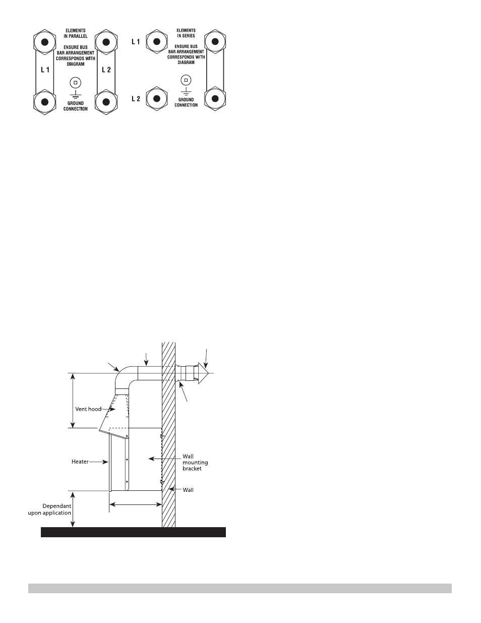
FIGURE 4 -
ELEMENTS IN PARALLEL
FIGURE 5 -
ELEMENTS IN SERIES
5.5
Ventilation
(i) The catalytic reaction in Cata-Dyne™
heaters occurs when natural gas or
propane reacts with oxygen to produce
water vapor, carbon dioxide and infrared
energy. Ventilation must be provided
to allow adequate supply of oxygen for
the reaction.
(ii) For every 1.0 ft
2
(0.093 m
2
) of heater
surface, 50 ft
3
/hr (1.42 m
3
/hr) of air
supply is required. For example, a WX 24
x 24 heater (20,000 Btu/hr / 5.857 kW)
would require 200 ft
3
/hr (5.66 m
3
/hr) of
air to ensure proper operation of the
Cata-Dyne™ heater.
(iii) To reduce the carbon dioxide and water
vapor concentrations in the building, a
vent hood assembly can be installed
to provide positive ventilation from the
heater (FIGURE 6).
15” approx.
11.5”
3” Flashing
3” Snow cap
3” Pipe
3” Elbow
FIGURE 6 - VENTILATION FROM HEATER