CCI Thermal Technologies G Series - Industrial Infrared Gas Catalytic Heater User Manual
Page 3
3
Separate Installation and Operation Instructions are available for industrial heating applications.
TABLE 4 - HEATER CLEARANCE
D - Radient Surface
C - Sides
A - Top
B - Bottom
Radient
Surface
Position
Heaters Up
To 12,000
Btu/hr
(3.514 kW)
Over 12,000
Up To
48,000
Btu/hr
(14.058 kW)
Over 48,000
Up To
60,000
Btu/hr
(17.572 kW)
All Heaters
Up To
60,000
Btu/hr
(17.572 kW)
Heaters Up
To 12,000
Btu/hr
(3.514 kW)
Over 12,000
Up To
48,000
Btu/hr
(14.058 kW)
Over 48,000
Up To
60,000
Btu/hr
(17.572 kW)
Heaters Up
To 12,000
Btu/hr
(3.514 kW)
Over 12,000
Up To
48,000
Btu/hr
(14.058 kW)
Over 48,000
Up To
60,000
Btu/hr
(17.572 kW)
in
mm
in
mm
in
mm
in
mm
in
mm
in
mm
in
mm
in
mm
in
mm
in
mm
Vertical (0°)
28
711
42
1067
60
1524
12
305
18
457
18
457
42
1067
7
178
12
305
18
457
0-45° up
28
711
42
1067
60
1524
12
305
18
457
32
813
54
1372
0
0
12
305
18
457
0-45° down
28
711
42
1067
60
1524
12
305
18
457
18
457
18
457
22
559
24
610
42
1067
5.3
Piping
(i) A main shut-off valve must be installed
upstream of all auxiliary heater controls.
(ii) The 100% safety shut-off valve (SSOV)
and appliance regulator (natural gas
heaters only) must be installed in the
upright position (horizontally).
(iii) The thermostatic temperature controller
should be installed with the dial shaft in
the horizontal position.
(iv) The maximum inlet pressure to the
100% safety shut-off valve, thermostatic
temperature control and appliance
regulator is 1/2 psi (3.4 kPa). If the
inlet pressure is higher than this, a low
pressure service regulator must be
installed upstream of these components.
(v) The maximum inlet pressure to the low
pressure service regulator (available
from CCI Thermal) is 250 psi (1.7 MPa).
If the inlet pressure is higher than this,
a high-pressure regulator must be
installed upstream.
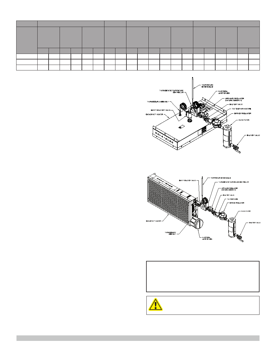
(vi) All components should be installed as
indicated in
FIGURE 2 (WX and BX
models) or FIGURE 3 (MKII model).
5.4
Electrical
(i) All wiring is to be installed in accordance
with the latest revisions of the Canadian
Electrical Code (CEC)/National Electrical
Code (NEC) and any applicable local codes.
(ii) It is desirable to install an indicating light
on all starting systems. This will reduce
the possibility of the power being left on
once the heater is started, which can
severely reduce the lifespan of the heater.
(iii) Ground connections for 120V and higher
voltage heaters are required as indicated
in FIGURE 4 and FIGURE 5.
(iv) The number of terminals in the junction
box can be two of four depending
on the number of elements used in
the fabrication of the heater. All MKII
models incorporate a single element
and therefore have only two terminals.
The connection procedure for the
different combinations is as described in
FIGURE 4 and FIGURE 5.
FIGURE 2 - TYPICAL NATURAL GAS INSTALLATION -
WX & BX MODELS ONLY
FIGURE 3 - TYPICAL NATURAL GAS INSTALLATION -
MKII MODEL ONLY
NOTE:
Gas appliance regulators and manual shut off valves
are required standard components for all CSA approved
heaters; they are available as optional accessories for
FM approved heaters.
CAUTION
INSTALL MKII SERIES HEATERS WITH
CONTROLS ON SIDES OR BOTTOM OF
HEATER ONLY.