Danger – Viking Pump TSM630.1: H-LL Universal Seal User Manual
Page 8
SECTION TSM 630.1
ISSUE
F
PAGE 8 OF 14
DANGER !
Before starting pump, be sure all drive
equipment guards are in place.
Failure to properly mount guards may
result in serious injury or death.
3. Coat idler pin with light oil and place idler and bushing
on idler pin in head. If replacing with carbon graphite
bushing,
Refer to “Installation of Carbon Graphite
Bushings”, page 11.
4. Using a .010 to .015 inch head gasket, install head and
idler assembly on pump. Pump head and casing were
marked before disassembly to insure proper reassembly.
If not, be sure idler pin, which is offset in pump head,
is positioned toward the equal distance between port
connections to allow for proper flow of liquid through
pump. If pump is equipped with jacketed headplate,
install at this time along with new gasket.
Tighten head capscrews evenly.
5. When assembling packed pump, use packing suitable
for liquid being pumped. Install packing, staggering the
joints from one side of shaft to other. Lubricate packing
rings with oil, grease, or graphite to aid assembly. Install
packing gland, capscrews, and nuts. Make sure gland is
installed square and nuts are tightened evenly. Tighten
nuts until packing gland is snug against packing.
6. Slide inner spacer collar over shaft with recessed end
facing rotor. H and HL size bearing spacer collars are
not recessed.
Place pair of half round rings on shaft and slide inner
bearing spacer collar over half round rings to lock them
in place. There is no pair of half round rings on the H
and HL size pumps.
7. Install the lip seal (lip toward end of shaft) in the bearing
housing and turn the bearing housing into the bracket.
8. Pack the ball bearing with grease, place on the shaft and
push or drive into place in housing.
9. Install the lipseal (with lip toward end of shaft) and
bearing spacer collar in the outer end cap and turn the
end cap into the bearing housing until tight against the
bearing. Lock in place with two set screws in the flange
of the bearing housing.
10. Put lockwasher and locknut on shaft. Insert length of
hardwood or brass through port opening between rotor
teeth to keep shaft from turning. Tighten locknut to 50-
70 ft. – lbs. Torque (H, HL) or 100-130 ft. – lbs. Torque
(K, KK, L, LQ, LL). Bend one tang of lockwasher into
slot of locknut. If tang does not line up with slot, tighten
locknut until it does. Failure to tighten locknut or engage
lockwasher tang could result in early bearing failure and
cause damage to pump.
Remove length of hardwood or brass from port opening.
11. Adjust pump end clearance as in “Thrust Bearing
Adjustment”, page 10.
12. Lubricate all grease fittings with multi-purpose grease,
NLGI #2.
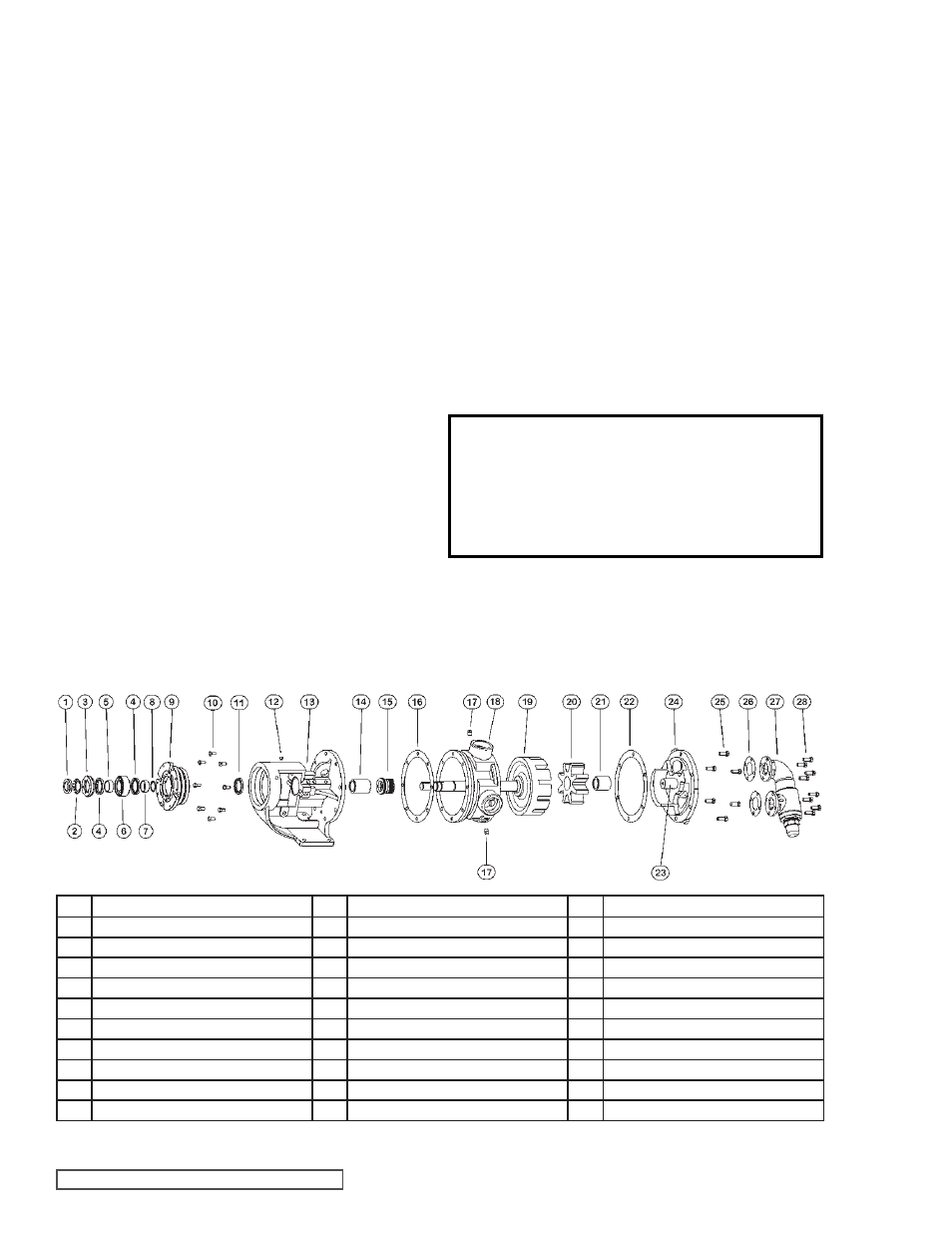
ITEM
NAME OF PART
ITEM
NAME OF PART
ITEM
NAME OF PART
1
Locknut
11
Lip Seal
21
Idler Bushing
2
Lockwasher
12
Grease Fitting
22
Head Gasket
3
End Cap
13
Bracket and Bushing Assembly
23
Idler Pin
4
Lip Seal
14
Bracket Bushing
24
Head and Idler Pin Assembly
5
Bearing Spacer Collar (Outer)
15
Mechanical Seal
25
Capscrew for Head
6
Ball Bearing
16
Bracket Gasket
26
Relief Valve Gasket
7
Bearing Spacer Collar (Inner)
17
Pipe Plug
27
Internal Relief Valve
8
Ring, Half Round (Not H, HL)
18
Casing (Tapped or Flanged)
28
Capscrew for Relief Valve
9
Bearing Housing
19
Rotor and Shaft
10
Capscrew for Bracket
20
Idler and Bushing Assembly
REPAIR: MODELS H, HL, K, KK, L, LQ AND LL
BEHIND THE ROTOR COMPONENT MECHANICAL SEAL PUMPS
FIGURE 8 - EXPLODED VIEW SERIES 4224B MODELS