Disassembly, Assembly – Viking Pump TSM630: H-LL Universal Seal User Manual
Page 9
SECTION TSM 630
ISSUE
H
PAGE 9 OF 12
1. Mark head and casing before disassembly to insure
proper reassembly. The idler pin, which is offset in pump
head, must be positioned toward and equal distance
between port connections to allow for proper flow of
liquid through the pump.
Remove head from pump. Do not allow idler to fall from
idler pin. Tilt top of head back when removing to prevent
this. Avoid damaging head gasket. If pump is furnished
with pressure relief valve, it need not be removed from
head or disassembled at this point.
Refer to Pressure
Relief Valve Instructions, page 11.
If pump has jacketed head plate, it will separate from
head when it is removed. The gasket between head and
jacket head plate must be totally removed. Use new
gasket when assembling pump.
2. Remove idler and bushing assembly.
3. Insert length of hardwood or brass through port opening
between rotor teeth to keep shaft from turning. Bend up
tang of lockwasher and with a spanner wrench, remove
locknut and lockwasher from shaft.
4. Loosen two setscrews in the face of the bearing housing
and remove the bearing housing assembly from the
bracket.
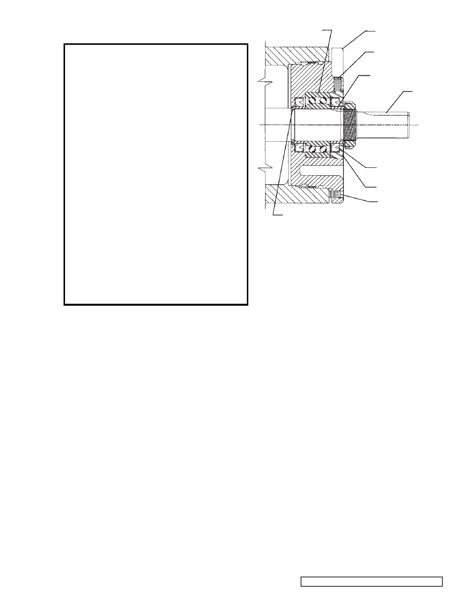
Refer to Figure 10.
5. Remove pair of half round rings under the inner spacer
collar from the shaft. There are no half round rings on
the “H” and “HL” size pumps.
6. Carefully remove rotor and shaft to avoid damaging
bracket bushing.
7. Loosen two radial setscrews in flange of bearing housing
and with a spanner wrench remove the outer end cap
with closure and outer bearing spacer collar.
8. Remove the double row ball bearing, closure and inner
bearing spacer collar from the bearing housing.
9. Remove the rotary member of the mechanical seal from
the rotor shaft. Remove the seal seat from the bracket.
10. Clean all parts thoroughly and examine for wear and
damage. Check lip seals, ball bearing, bushings, and
idler pin and replace if necessary. Check all other
parts for nicks, burrs, excessive wear and replace if
necessary.
Wash bearings in clean solvent. Blow out bearings with
compressed air. Do not allow bearings to spin; turn them
slowly by hand. Spinning bearings will damage race and
balls. Make sure bearings are clean, then lubricate with
light oil and check for roughness. Roughness can be
determined by turning outer race by hand.
11. Casing can be checked for wear or damage while
mounted on bracket.
HALF ROUND
RINGS
FIGURE 10
END CAP
DISASSEMBLY
DANGER !
Before opening any Viking pump liquid
chamber (pumping chamber, reservoir,
relief valve adjusting cap fitting, etc.)
Be sure:
1. That any pressure in the chamber has
been completely vented through the
suction or discharge lines or other
appropriate openings or connections.
2. That the driving means (motor,
turbine, engine, etc.) has been “locked
out” or made non-operational so that
it cannot be started while work is
being done on pump.
3. That you know what liquid the
pump has been handling and the
precautions necessary to safely
handle the liquid. Obtain a material
safety data sheet (MSDS) for the
liquid to be sure these precautions
are understood.
Failure to follow above listed
precautionary measures may result in
serious injury or death.
LIPSEAL
SPACER COLLAR
SETSCREW
SHAFT
SETSCREW
BEARING HOUSING
BALL BEARING
1. Install bracket bushing. If bracket bushing has a
lubrication groove, install bushing with groove at 6.00
o’clock position in bracket. If carbon graphite,
Refer to
Installation of Carbon Graphite Bushings, page 11.
Make sure slots in the face of the bushing are towards
rotor end of the bracket.
2. Clean rotor shaft and seal housing bore. Make sure they
are free of dirt, grit and scratches. Gently radius leading
edge of shaft diameter over which seal is to be placed.
Never touch mechanical seal faces with anything except
clean hands or clean cloth. Minute particles can scratch
the seal faces and cause leakage.
ASSEMBLY