Pressure relief valve instructions, Disassembly, Assembly important – Viking Pump TSM430: HL-N 34/434 User Manual
Page 8
SECTION TSM 430
ISSUE
G
PAGE 8 OF 9
PRESSURE RELIEF VALVE
INSTRUCTIONS
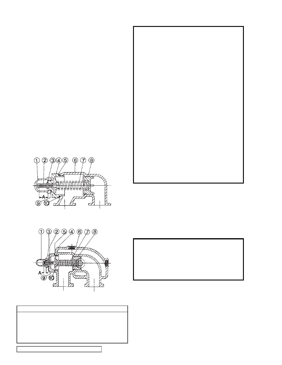
FIGURE 11
PLAIN VALVE
VALVE - LIST OF PARTS
1. Valve Cap
6. Valve Body
2. Adjusting Screw
7. Valve Spring
3. Lock Nut
8. Poppet
4. Spring Guide
9. Cap Gasket
5. Bonnet
10 Bonnet Gasket
Series 34 and 434 jacketed pumps may be furnished with
a relief valve head and a plain or jacketed relief valve as
illustrated in
Figures 10 and 11.
FIGURE 11
JACKETED VALVE
DANGER !
Before opening any Viking pump liquid
chamber (pumping chamber, reservoir,
relief valve adjusting cap fitting, etc.)
Be sure:
1. That any pressure in the chamber has
been completely vented through the
suction or discharge lines or other
appropriate openings or connections.
2. That the driving means (motor,
turbine, engine, etc.) has been “locked
out” or made non-operational so that
it cannot be started while work is
being done on pump.
3. That you know what liquid the
pump has been handling and the
precautions necessary to safely
handle the liquid. Obtain a material
safety data sheet (MSDS) for the
liquid to be sure these precautions
are understood.
Failure to follow above listed
precautionary measures may result in
serious injury or death.
DISASSEMBLY
7. When converting an existing installation to a mechanical
seal, special attention must be placed on the condition
of the pump. All pumps should be inspected to make
sure the rotor shaft is in good condition. Any shaft wear
due to packing will result in mechanical seal leakage.
In general, the rotor and shaft assembly should be
replaced. N size pumps can use the same rotor bearing
sleeve assembly without modification. Outboard face
of this assembly will need to be cleaned to make sure
there is a good surface for the mechanical seal to seal
against.
8. Most asphalt pumps are V-Belt driven. Packing is quite
tolerant of any misalignment but mechanical seals are
not. Make sure sheaves are aligned properly
(see TSM
000) and that the rotor shaft is properly supported with a
pillow block bearing. It is also important to make sure the
mechanical seal is properly aligned with the rotor shaft.
This is done at the time of seal installation. Be sure to
recheck alignment when the rotor shaft is inserted in the
pillow block bearing.
ASSEMBLY
IMPORTANT
In ordering parts for relief valve on head, always be sure
to give Model and Serial Number of pump as it appears on
nameplate and the name of the part wanted. When ordering
springs, be sure to give the pressure setting desired.
Follow the procedure outlined under Disassembly in reverse
order.
If valve is removed for repairs, be sure to replace in same
position. The valve cap should point towards the suction
port.
CAUTION !
Before starting the pump, be sure all drive
equipment guards are in place.
Failure to properly mount guards may
result in serious injury or death.