Viking Pump TSM343.1: Vi-Corr Mag Drive User Manual
Page 4
TSM 343.1 ISSUE D PAGE 4 OF 13
2.
Check Pump alignment (See page 3).
3.
Check piping to be sure there is no strain on the pump
casing.
4.
Rotate the pump shaft by hand to be sure it turns freely.
55. Motor has been jogged and is running in the correct
direction. Refer to "General" on page 2.
6. Pressure relief valve is installed properly.
7. Suction piping is connected and tight, and valves are
open.
8. Make sure discharge piping is connected and tight,
valves are open and, and end of shaft is below liquid
level.
9. All guards are in place.
10. The above checklist is a general guideline to be used
prior to starting pump. Since Viking pump cannot foresee
every application for our product and possible system
design, final responsibility is with the user. The pump
must be utilized within the catalog specifications and the
pump system must be designed to provide safe working
conditions.
Push the "start" button. Pump should begin to deliver liquid
within 15 seconds!
If the pump does not deliver liquid, push the stop button.
Do
not run the pump without liquid flow longer than 30
seconds because pump or coupling could be damaged
or ruined.
Review steps just outlined. Consider what suction and
discharge gauges indicate. If everything appears in order, put
more liquid in the pump suction port. See item 6 on page 3.
Push the start button. If nothing happens within 30 seconds,
stop the pump. The pump is not a compressor and will not
build up much air pressure. It may be necessary to vent the
discharge line until liquid begins to flow. Use a safe venting
procedure especially when handling hazardous liquids.
If the pump still does not deliver liquid, consider one or more
of the following:
1. Suction line air leaks; vacuum gauge reading should help
determine if this is the problem.
2. End of suction pipe not submerged deep enough in liquid.
3. Suction lift is too great or suction piping is too small.
4. Liquid is vaporizing in the suction line before it gets to the
pump.
5. Magnetic coupling is decoupling for some reason.
If after consideration of these points, the pump still does not
deliver liquid, review all points given under
START UP and
read through the
TROUBLESHOOTING guide and try again.
If pump still will not deliver liquid, contact your Viking Pump
supplier.
SUGGESTED REPAIR TOOLS: The following are required
to properly repair a RP Series Mag Drive pump. The tools are
in addition to standard mechanics tools such as open end
wrenches, pliers, screw drivers, etc. Most of the items can be
obtained from an industrial supply house.
1. Soft face hammer
2. Allen wrenches
3. Internal snap ring pliers (for bearing carriers only) 2-810-
029-047-999 (Truarc No. 0500)
4. External snap ring pliers 2-810-029-375 (Truarc No. 0400)
4. Arbor press
5. Torque wrench
DISASSEMBLY Of MD-A2, MD-A8,
MD-B15, or MD-B40 COUPLINGS
1. Read all of the instructions before proceeding with
disassembly of the coupling and/or pump. Remove
piping to ports and remove the mounting capscrews
securing pump to bracket. Support larger pumps with
overhead hoist if possible. Remove pump from coupling
bracket. See FIGURE 6 on page 4.
2. Canister will probably be full of liquid, use care while
removing from pump and pull straight off. Loosen both
setscrews and pull off inner magnet assembly. MD-A2
and MD-A8 couplings require removing the pipe plug in
pump bracket to gain access to the setscrews holding
the inner magnet.
Don't forget this is a very powerful magnet. Do not
remove O-ring on bracket unless you plan to replace -
especially the encapsulated O-rings. Follow instructions
in
ASSEMBLY for installation of a new Teflon®
encapsulated O-ring.
3. You should be able to visually inspect other magnets
from end of bracket. If removal is necessary, start by
removing (4) capscrews and separating from motor or
bearing carrier. Loosen setscrews in outer magnet
assembly to pull assembly off shaft.
PAGE 4 Of 13
ISSUE
C
SECTION TSM 343.1
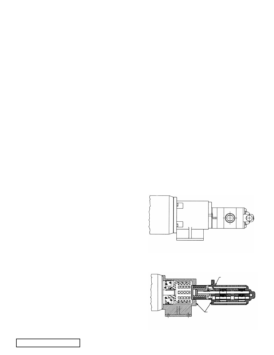
fIGURE 5
RP-80732 - MD-B15 with motor
PLACE HANDS BACK HERE
CAUTION: DO NOT PLACE fINGERS
HERE AT ANY TIME
fIGURE 6
Typical Pump Removal from Coupling Bracket
2.
Check Pump alignment (See page 3).
3.
Check piping to be sure there is no strain on the pump
casing.
4.
Rotate the pump shaft by hand to be sure it turns freely.
55. Motor has been jogged and is running in the correct
direction. Refer to "General" on page 2.
6. Pressure relief valve is installed properly.
7. Suction piping is connected and tight, and valves are
open.
8. Make sure discharge piping is connected and tight,
valves are open and, and end of shaft is below liquid
level.
9. All guards are in place.
10. The above checklist is a general guideline to be used
prior to starting pump. Since Viking pump cannot foresee
every application for our product and possible system
design, final responsibility is with the user. The pump
must be utilized within the catalog specifications and the
pump system must be designed to provide safe working
conditions.
Push the "start" button. Pump should begin to deliver liquid
within 15 seconds!
If the pump does not deliver liquid, push the stop button.
Do
not run the pump without liquid flow longer than 30
seconds because pump or coupling could be damaged
or ruined.
Review steps just outlined. Consider what suction and
discharge gauges indicate. If everything appears in order, put
more liquid in the pump suction port. See item 6 on page 3.
Push the start button. If nothing happens within 30 seconds,
stop the pump. The pump is not a compressor and will not
build up much air pressure. It may be necessary to vent the
discharge line until liquid begins to flow. Use a safe venting
procedure especially when handling hazardous liquids.
If the pump still does not deliver liquid, consider one or more
of the following:
1. Suction line air leaks; vacuum gauge reading should help
determine if this is the problem.
2. End of suction pipe not submerged deep enough in liquid.
3. Suction lift is too great or suction piping is too small.
4. Liquid is vaporizing in the suction line before it gets to the
pump.
5. Magnetic coupling is decoupling for some reason.
If after consideration of these points, the pump still does not
deliver liquid, review all points given under
START UP and
read through the
TROUBLESHOOTING guide and try again.
If pump still will not deliver liquid, contact your Viking Pump
supplier.
SUGGESTED REPAIR TOOLS: The following are required
to properly repair a RP Series Mag Drive pump. The tools are
in addition to standard mechanics tools such as open end
wrenches, pliers, screw drivers, etc. Most of the items can be
obtained from an industrial supply house.
1. Soft face hammer
2. Allen wrenches
3. Internal snap ring pliers (for bearing carriers only) 2-810-
029-047-999 (Truarc No. 0500)
4. External snap ring pliers 2-810-029-375 (Truarc No. 0400)
4. Arbor press
5. Torque wrench
DISASSEMBLY Of MD-A2, MD-A8,
MD-B15, or MD-B40 COUPLINGS
1. Read all of the instructions before proceeding with
disassembly of the coupling and/or pump. Remove
piping to ports and remove the mounting capscrews
securing pump to bracket. Support larger pumps with
overhead hoist if possible. Remove pump from coupling
bracket. See FIGURE 6 on page 4.
2. Canister will probably be full of liquid, use care while
removing from pump and pull straight off. Loosen both
setscrews and pull off inner magnet assembly. MD-A2
and MD-A8 couplings require removing the pipe plug in
pump bracket to gain access to the setscrews holding
the inner magnet.
Don't forget this is a very powerful magnet. Do not
remove O-ring on bracket unless you plan to replace -
especially the encapsulated O-rings. Follow instructions
in
ASSEMBLY for installation of a new Teflon®
encapsulated O-ring.
3. You should be able to visually inspect other magnets
from end of bracket. If removal is necessary, start by
removing (4) capscrews and separating from motor or
bearing carrier. Loosen setscrews in outer magnet
assembly to pull assembly off shaft.
PAGE 4 Of 13
ISSUE
C
SECTION TSM 343.1
fIGURE 5
RP-80732 - MD-B15 with motor
PLACE HANDS BACK HERE
CAUTION: DO NOT PLACE fINGERS
HERE AT ANY TIME
fIGURE 6
Typical Pump Removal from Coupling Bracket
5.
6.