Viking Pump TSM343.1: Vi-Corr Mag Drive User Manual
Page 10
TSM 343.1 ISSUE D PAGE 10 OF 13
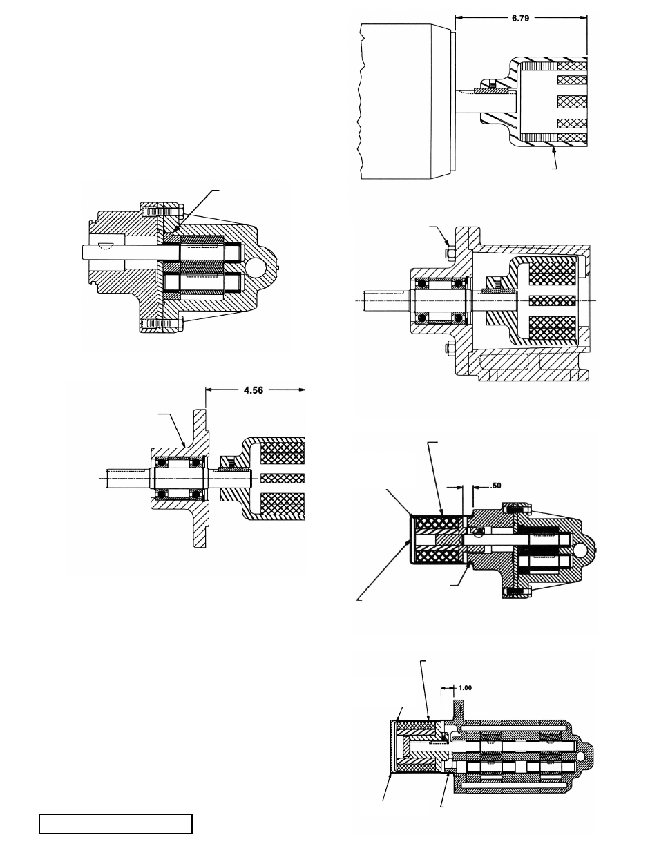
1. Inspect magnets for any metal objects attached to the
magnets. Remove any foreign material. Locate outer
magnet assembly per drawing. Reference point for MD-
A2 & MD -A8 is the back edge of the "C" face. See Figure
17. Apply loctite to setscrew threads and tighten both
setscrews onto motor or bearing carrier shaft. The
bearing carrier housing features a machined step on its
mounting flange, which is the reference point for setting
the position of the outer magnet.
2. Mount bracket to motor (or bearing carrier to footed
bracket) and secure with 4 capscrews. See Figure 18.
Reach in and rotate magnets by hand to make sure there
is no interference. If rubbing occurs, check dimensions
(see Figures 16 and 17) or contact factory.
3. Place inner magnet assembly onto pump shaft and set
according to figures. See Figure 19, or (See figure 20).
Place Loctite on threads of the two setscrews then
tighten. Check the dimension again, then turn the pump
over a couple of times to make sure it turns freely. Inspect
magnet and make sure it has not picked up any foreign
particles which could damage the pump. Make sure
bracket O-ring is in good condition and installed. Place
canister onto pump and press until canister is in contact
with pump bracket.
PAGE 10 Of 13
ISSUE
C
SECTION TSM 343.1
CASING NOTCH
fIGURE 15
BEARING CARRIER
ASSEMBLY
fIGURE 16
MD-A2 and MD-A8
STANDARD
"C" FACE
MOTOR
WITH 8-1/2"
RABBIT
OR
BEARING
CARRIER
OUTER MAGNET
ASSEMBLY
fIGURE 17
MD-B15 and MD-B40
CAPSCREW
(& NUT)
fIGURE 18
Coupling Bracket and Bearing Carrier for
MD-A2 and MD-A8
THIS SURFACE MUST BE FREE OF ANY
FOREIGN METAL PARTICLES PRIOR TO
ASSEMBLY INTO BRACKET
INNER
MAGNET
ASSEMBLY
CANISTER
STATIC O-RING
fIGURE 19
MD-A2 and MD-A8
THIS SURFACE MUST BE FREE OF ANY
FOREIGN METAL PARTICLES PRIOR TO
ASSEMBLY INTO BRACKET
INNER MAGNET
ASSEMBLY
CANISTER
STATIC O-RING
fIGURE 20
MD-B15 and MD-B40