Special pump designs, Pressure adjustment, Important – Viking Pump TSM320.1: C-FH 56/456 User Manual
Page 6: Pressure relief valve
SECTION TSM 320.1
ISSUE
E
PAGE 6 OF 7
The relief valve is a pressure device to protect the pump
and motor against excessive pressure. A pump without a
properly set pressure relief valve operating against a closed
discharge line could build up enough pressure to damage
the pump or motor.
The pressure setting is increased by turning the adjusting
screw in and decreased by turning the adjusting screw out.
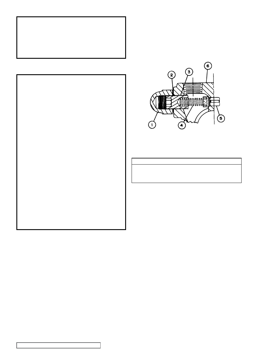
fIgURE 7
PRESSURE RELIEF VALVE - C, F, FH SIZE
VaLVE - LIST Of PaRTS
1.
Adjusting Screw Cap
4.
Spring
2.
Gasket for Cap
5.
Poppet
3.
Adjusting Screw
6.
Casing
DaNgER !
Before starting pump, be sure all drive
equipment guards are in place.
failure to properly mount guards may
result in serious injury or death.
SPECIaL PUMP DESIgNS
Pumps furnished with a PTFE Mechanical seal require a
special rotor and shaft with drive pin installed for positive drive
of the rotating member. All other assembly and disassembly
instructions are the same.
PRESSURE aDJUSTMENT
DaNgER !
Before opening any Viking pump liquid
chamber (pumping chamber, reservoir,
relief valve adjusting cap fitting, etc.)
Be sure:
1. That any pressure in the chamber has
been completely vented through the
suction or discharge lines or other
appropriate openings or connections.
2. That the driving means (motor,
turbine, engine, etc.) has been “locked
out” or made non-operational so that
it cannot be started while work is
being done on pump.
3. That you know what liquid the
pump has been handling and the
precautions necessary to safely
handle the liquid. Obtain a material
safety data sheet (MSDS) for the
liquid to be sure these precautions
are understood.
failure to follow above listed
precautionary measures may result in
serious injury or death.
If a new spring is installed or if the pressure setting of the
pressure relief valve is to be changed from that which the
factory has set, the following instructions must be carefully
followed.
1. Carefully remove the valve cap, which covers the
adjusting screw.
Loosen the locknut, which locks the adjusting screw
so pressure setting will not change during operation of
the pump.
2. Install a pressure gauge in the discharge line for the
actual adjustment operation.
3. Turn the adjusting screw in to increase pressure and out
to decrease pressure.
4. With the discharge line closed at a point beyond the
pressure gauge, the gauge will show the maximum
pressure valve will allow while the pump is in operation.
IMPORTaNT
In ordering parts for the pressure relief valve, always give
the model number and serial number of the pump as it
appears on the nameplate and the name of the part wanted.
When ordering springs, be sure to give the pressure setting
desired.
PRESSURE RELIEf VaLVE