Viking Pump TSM320.1: C-FH 56/456 User Manual
Page 4
SECTION TSM 320.1
ISSUE
E
PAGE 4 OF 7
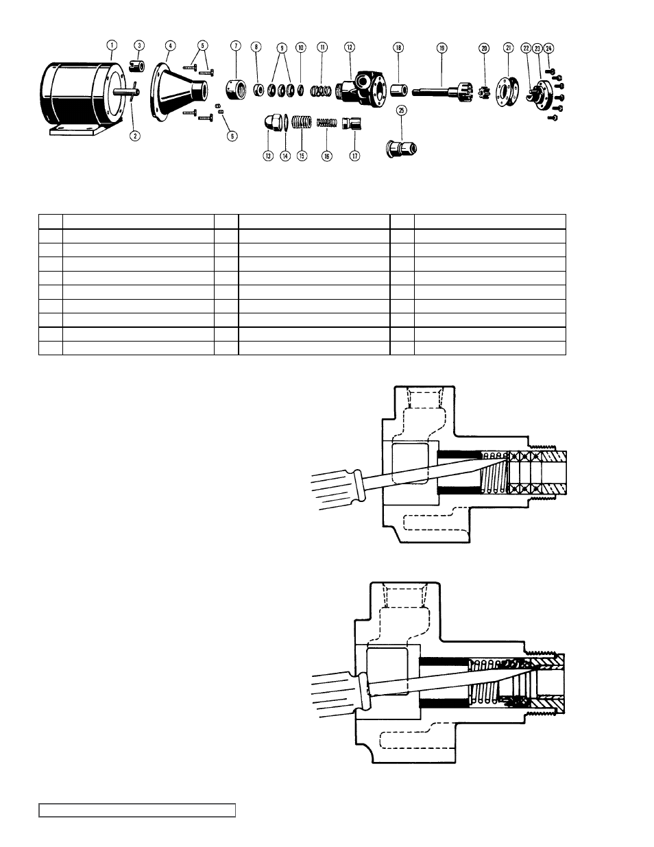
fIgURE 2
EXPLODED VIEW SERIES 56 aND 456
ITEM
NaME Of PaRT
ITEM
NaME Of PaRT
ITEM
NaME Of PaRT
1
Electric Motor
10
Inner Packing Gland (Series 56 only)
19
Rotor and Shaft Assembly
2
Motor Shaft Pin
11
Packing Spring (Series 56 only)
20
Idler
3
Coupling with Setscrew
12
Casing
21
Head Gasket
4
Mounting Bracket
13
Cap
22
Idler Pin
5
Capscrew for Bracket to Motor
14
Gasket for Cap
23
Head
6
Setscrew for Pump to Bracket
15
Adjusting Screw
24
Capscrew for Head
7
Packing Nut
16
Spring
25
Mechanical Seal (Series 456 only)
8
Outer Packing Gland (Series 56 only)
17
Poppet
9
Packing (Series 56 only)
18
Casing Bushing
1. Remove the capscrews and the head from the pump.
It may be necessary to apply a slight pressure on the
drive end of the rotor shaft to free the head from the
casing.
DO NOT PRY the head from the casing as this
may damage and mar the gasket surfaces.
2. Remove idler from idler pin. If the idler pin is worn, both
the head and idler pin, and idler should be replaced.
3. Next, completely remove the rotor and shaft from the
casing by exerting pressure on the drive end of the
shaft.
4. Remove the packing nut.
5. The pump is now ready for removal of packing or
mechanical seal.
Refer to figure 3 or 4 for example. It
is recommended a new mechanical seal or packing be
used every time a pump is completely disassembled.
All parts should be examined for wear before the pump is
put together. When making major repairs, such as replacing
a rotor and shaft, it is usually considered advisable to also
install a new casing bushing.
fIgURE 3
fIgURE 4
MEChaNICaL
SEaL (456)
PaCKED
(56)