Disassembly – Viking Pump TSM211: F-G 724/4724 User Manual
Page 5
SECTION TSM 211
ISSUE
D
PAGE 5 OF 8
DISASSEMBLY
1. CAUTION: When the head is being removed from the
pump
(See figure 2), the idler usually stays on the
idler pin, but will fall off if the inside of the head is tilted
downward. A fall on a hard surface can damage the idler.
If the idler should fall, check carefully and file or stone all
nicked or rough places before reassembly.
Remove the head from the pump. If the pump has a
relief valve on head, the valve may have to be removed
before removing the head.
2. Remove the head gasket. If a new gasket is not
available, the original gasket may be re-used provided it
was not damaged when removing the pump head.
3. Remove idler from the idler pin. If the idler pin is worn,
both the idler pin and idler bushing should be replaced.
On the F & FH size the idler & bushing assembly must
be replaced. The idler pin may be removed from the
head by pressing the pin out with a suitable press.
4. Remove the bearing locknut with a spanner wrench
using a suitable wrench on the flat of the shaft to hold the
shaft from turning. A piece of brass rod or wood inserted
in the port area and between the rotor teeth will also hold
the shaft from turning. Remove this piece of brass after
locknut is removed.
5. Remove bracket capscrews and disassemble bracket
from casing.
6. REMAININg DISASSEMBLY PROCEDURE for the
Series 724 packed pump.
(Refer to figure 4).
Remove the packing gland nut, packing gland retainer
washer, and split packing gland halves. The internal
retaining ring, does not need to be removed at this point.
To remove the rotor and shaft, push or tap with a soft
hammer toward the head. The packing and packing
retainer washer can now be removed.
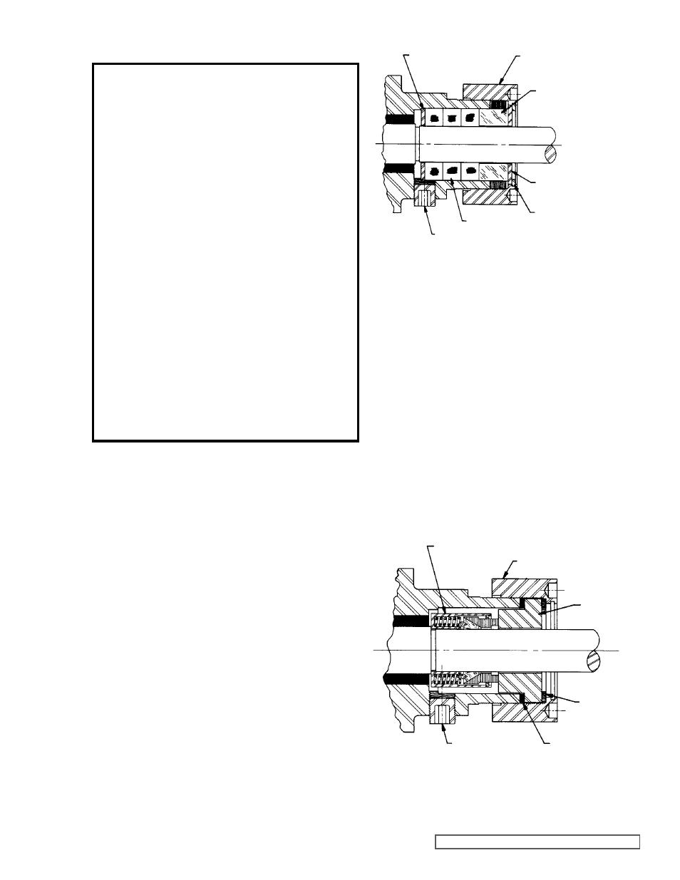
7. REMAININg DISASSEMBLY PROCEDURE for the
Series 4724 mechanical seal pump.
(Refer to fig.
5). Remove the 1/8” socketed head pipe plug on the
casing and loosen the two Allen head setscrews on the
mechanical seal.
fIgURE 4
PACKINg AREA CROSS SECTION
(SERIES 724)
fIgURE 5
MECHANICAL SEAL AREA CROSS SECTION
(SERIES 4724)
DANgER !
Before opening any Viking pump liquid
chamber (pumping chamber, reservoir,
relief valve adjusting cap fitting, etc.)
Be sure:
1. That any pressure in the chamber has
been completely vented through the
suction or discharge lines or other
appropriate openings or connections.
2. That the driving means (motor,
turbine, engine, etc.) has been “locked
out” or made non-operational so that
it cannot be started while work is
being done on pump.
3. That you know what liquid the
pump has been handling and the
precautions necessary to safely
handle the liquid. Obtain a material
safety data sheet (MSDS) for the
liquid to be sure these precautions
are understood.
failure to follow above listed
precautionary measures may result in
serious injury or death.
PACKINg
PACKINg gLAND
RETAININg WASHER
PACKINg
RETAININg
WASHER
INTERNAL
RETAININg RINg
PACKINg
gLAND NUT
SPLIT PACKINg
gLAND HALVES
PIPE PLUg
PACKINg gLAND NUT
PIPE PLUg
PTfE gASKET
gASKET
SEAL SEAT
ROTARY MEMBER