Thrust bearing adjustment, Installation of carbon graphite bushings, Danger – Viking Pump TSM144: GG-AL 495/4195 User Manual
Page 8
SECTION TSM 144
ISSUE
H
PAGE 8 OF 10
G, GG, H, HJ, HL: Drive the bearing into the bore. Tap
the inner race with a brass bar and
lead hammer to position bearing.
Install the inner snap ring.
AS, AK, AL: Install the bearing retainer washer over
the shaft before installing the ball bearing.
Install the ball bearing in the casing. Drive
the bearing into the bore. Tap the inner
race with a brass bar and lead hammer to
position the bearing.
13. H, HJ, HL: Install the shaft snap ring in groove in
the shaft. See
Figure 9, page 6.
AS, AK, AL: Install the bearing spacer over the shaft
and against the single row ball bearing.
See
Figure 10, page 6.
14. G, GG, H, HJ, HL: Install the ball bearing into the bearing
housing See
Figure 9, page 6. Install
the snap ring into bearing housing to
retain ball bearing. This snap ring has
a tapered edge to fit tapered groove in
bearing housing. The tapered edge is
located away from the ball bearing.
AS, AK, AL: Install the ball bearing into the bearing
housing. Install the lip seal in the bearing
housing end cap. The lip should face
towards the end of the shaft. Put the bearing
spacer collar in the lip seal and install in
the bearing housing and tighten the set
screws securely. See
Figure 10, page 6.
15. Insert a brass bar or piece of hardwood through the port
opening between the rotor teeth to keep the shaft from
turning.
16. Start the thrust bearing assembly into casing. Turn by
hand until tight. This forces the rotor against the head.
Replace and tighten the locknut on shaft.
17. Remove the brass bar or hardwood from port opening.
18. Adjust pump end clearance, refer to “Thrust Bearing
Adjustment”.
Loosen the two screws in the face of the thrust bearing
assembly.
If the shaft cannot be rotated freely, turn the thrust bearing
assembly counterclockwise until the shaft can be turned
easily.
To set end clearance:
1. While turning the rotor shaft, rotate the thrust bearing
assembly clockwise until a noticeable drag occurs. This
is zero end clearance.
2. Mark the position of the bearing housing with respect to
the casing.
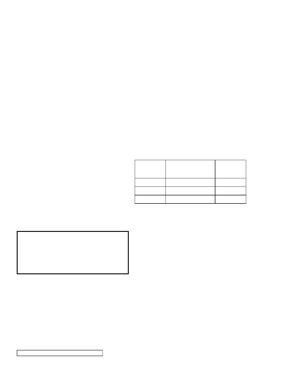
3. Rotate the thrust bearing assembly counterclockwise the
distance listed below as measured on outside of bearing
housing.
4. After the adjustment is made, tighten the two setscrews
in the face of the bearing housing assembly to secure
the position.
For viscosities above 2500 SSU, add additional end
clearance (0.004” for G, GG, H, HJ and HL size pumps
and 0.005” for AS, AK and AL size pumps).
When installing the carbon graphite bushings, extreme care
must be taken to prevent breaking. Carbon graphite is a brittle
material and is easily cracked. If cracked, the bushing will
quickly disintegrate. Using a lubricant and adding a chamfer
on the bushing and the mating part will help in installation.
The additional precautions listed below must be followed for
proper installation:
1. A press must be used for installation.
2. Be certain the bushing is started straight.
3. Do not stop pressing the operation until the bushing is in
the proper position, as starting and stopping may result
in a cracked bushing.
4. Check the bushing for cracks after installation.
DANGER !
Before starting pump, be sure all drive
equipment guards are in place.
Failure to properly mount guards may
result in serious injury or death.
THRUST BEARING ADJUSTMENT
See
Figures 9 and 10.
PUMP
SIZE
DISTANCE IN INCHES
ON O.D. OF BEARING
HOUSING
STANDARD
END
CLEARANCE
G, GG
0.44” (7/16”)
.003
H, HJ , HL
0.56” (9/16”)
.003
AS , AK , AL
0.5” (1/2”)
.003
INSTALLATION OF CARBON
GRAPHITE BUSHINGS