Viking Pump TSM144: GG-AL 495/4195 User Manual
Page 6
SECTION TSM 144
ISSUE
H
PAGE 6 OF 10
10. The rotor and shaft can now be removed by tapping on
the end of the shaft with a lead hammer or, if using a
regular hammer, use a piece of hardwood between the
shaft and hammer. The rotary member of the seal will
come out with the rotor and shaft.
11. AS, AK, AL: Remove the bearing retainer washer. The
washer may have stayed with the rotor and
shaft when removed or is against the ball
bearing. See
Figure 10.
12. Remove the mechanical seal rotary member and spring
from the rotor and shaft assembly.
13. G, GG, H, HJ, HL: Remove the inner snap ring and
single row ball bearing from the casing.
AS, AK, AL: Remove the single row ball bearing from
the casing.
14. Remove the seal seat or stationary part of the seal from
the casing.
15. Disassemble the thrust bearing assembly.
G, GG, H, HJ, HL: Remove the outer snap ring from
the bearing housing and remove the
ball bearing. See
Figure 9.
AS, AK, AL: Loosen the two setscrews in the flange
outside diameter. Rotate the end cap and
lip seal counterclockwise and remove.
Remove the ball bearing. See
Figure 10.
The casing should be examined for wear, particularly in the
area between the ports. All parts should be checked for wear
before the pump is put together.
When making major repairs, such as replacing a rotor and
shaft; it is advisable to also install a new mechanical seal,
head and idler pin, idler and bushing. See
“Installation of
Carbon Graphite Bushings,” page 8.
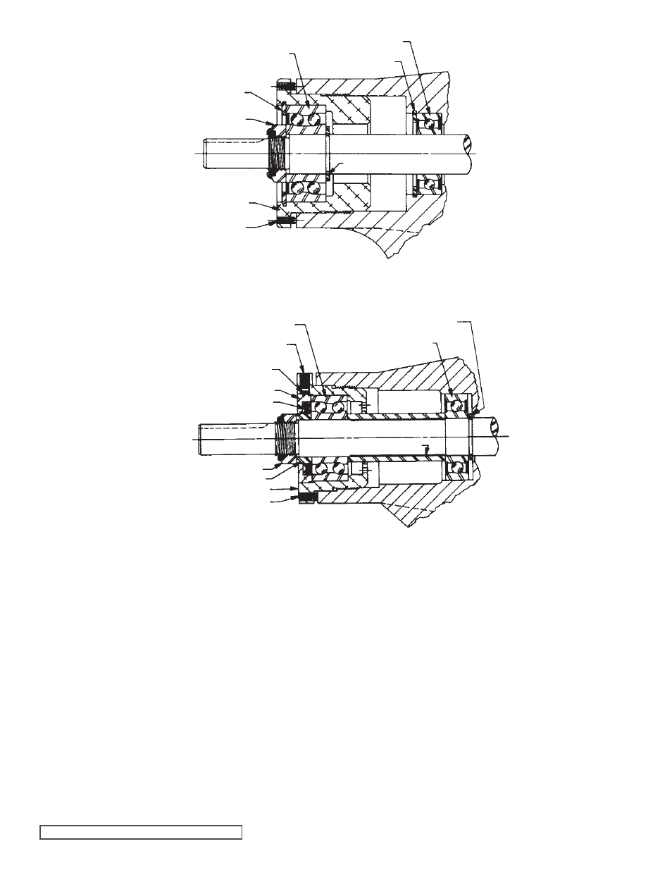
SHAFT SNAP RING*
OUTER BALL BEARING
BEARING HOUSING
INNER SNAP RING
INNER BALL BEARING
SETSCREW
SHAFT
OUTER SNAP RING
LOCKNUT
FIGURE 9 - THRUST BEARING ASSEMBLY G, GG, H, HJ AND HL SIZES
FIGURE 10 - THRUST BEARING ASSEMBLY AS, AK AND AL SIZES
BEARING RETAINER WASHER
BEARING SPACER
SETSCREW
LOCKNUT
LIP SEAL
END CAP
NYLON INSERT
SHAFT
INNER BALL BEARING
BEARING HOUSING
SETSCREW
BALL BEARING
BEARING SPACER COLLAR
* NOT USED ON
G & GG SIZE PUMPS