Disassembly – Viking Pump TSM142.1: H-LL 225/4225 User Manual
Page 5
SECTION TSM 142.1
ISSUE
F
PAGE 5 OF 13
DISASSEMBLY
DANgER !
Before opening any Viking pump liquid
chamber (pumping chamber, reservoir,
relief valve adjusting cap fitting, etc.)
Be sure:
1. That any pressure in the chamber has
been completely vented through the
suction or discharge lines or other
appropriate openings or connections.
2. That the driving means (motor,
turbine, engine, etc.) has been
“locked out” or made non-operational
so that it cannot be started while
work is being done on pump.
3. That you know what liquid the
pump has been handling and the
precautions necessary to safely
handle the liquid. Obtain a material
safety data sheet (MSDS) for the
liquid to be sure these precautions
are understood.
failure to follow above listed
precautionary measures may result in
serious injury or death.
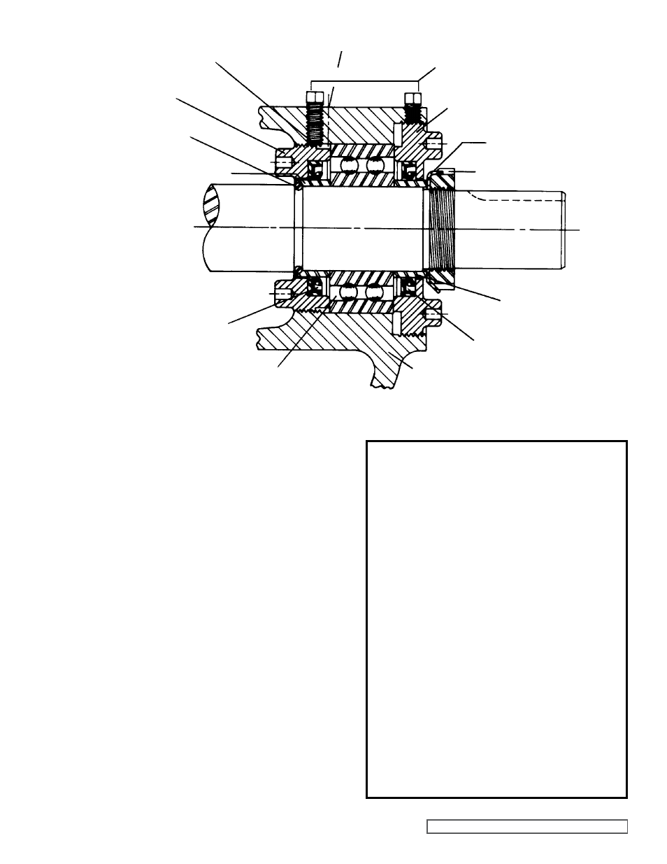
gREASE fITTINg LOCATION
INNER SPACER COLLAR
OUTER SPACER COLLAR
LOCKWASHER
SETSCREWS
OUTER END CAP
LOCKNUT
INNER LIP SEAL
HALf ROUND RINgS
INNER END CAP
NYLON INSERT
SHAfT
BALL BEARINg
BRACKET
OUTER LIP SEAL
fIgURE 5
1. Mark head and casing before disassembly to insure
proper reassembly. The idler pin, which is offset in pump
head, must be positioned toward and equal distance
between port connections to allow for proper flow of
liquid through pump.
Remove head from pump.
Do not allow idler to fall
from idler pin. Tilt top of head back when removing
to prevent this. Avoid damaging head gasket. If pump
is furnished with pressure relief valve, it need not be
removed from head or disassembled at this point.
Refer
to Pressure Relief Valve Instructions, page 12.
If pump has jacketed head plate, it will separate from
head when it is removed. The gasket between head and
jacket head plate must be totally removed. Use new
gasket when assembling pump.
2. Remove idler and bushing assembly.
3. Insert length of hardwood or brass through port opening
between rotor teeth to keep shaft from turning. Bend up
tang of lockwasher and with a spanner wrench remove
locknut and lockwasher from shaft.
4. Remove packing gland nuts.