13 removing the handle from a p type valve, Figure 5: manual valve on a standoff, Figure 6: p type valve with an svh handle 6 – VICI Two position Standard electric User Manual
Page 8
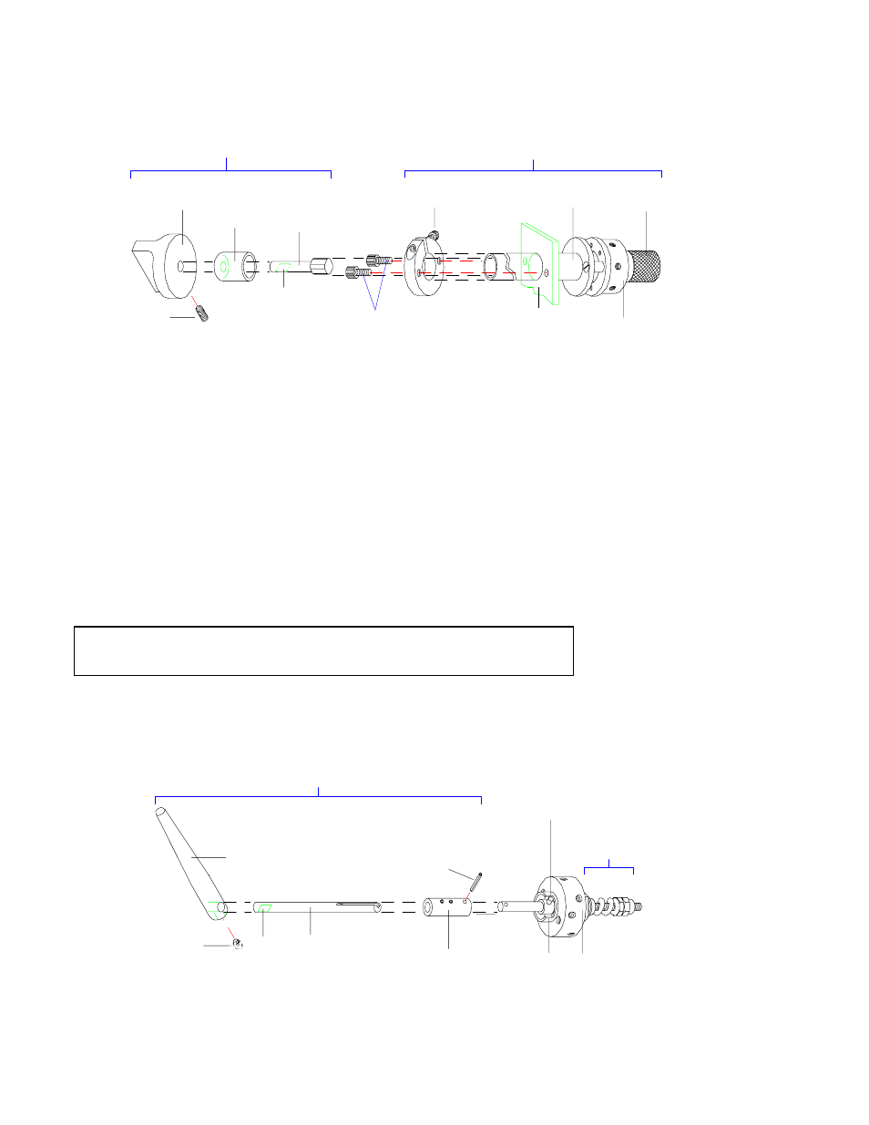
4.13 Removing the Handle from a P Type Valve
These types of valves have a 1-1/8" metal rotor shaft that connects to the handle.
1.
Rotate the knob counterclockwise so the valve is positioned properly for
later installation on the electric actuator.
2.
See Figure 6. Remove the black handle by sliding its shaft out of the
coupling.
3.
Place the coupling in a bench vise with the side with only one hole facing
up. Use a hammer and punch to remove the roll pin which connects the
coupling to the valve rotor shaft. Pull the coupling off of the shaft.
CAUTION: Do not hold the valve body in the vise when removing the
coupling. Valve damage will result.
4.
Proceed to Section 4.2 for closemount assembly, or Section 4.3 if the valve
will go on a standoff before being installed on the actuator.
KNOB ASSEMBLY
STANDOFF ASSEMBLY (Length varies)
WITH VALVE ATTACHED
WK/KNOB
RETAINER
HWSC-SS8-5B/
SET-SCREW
MHA/MANUAL
HANDLE
ADAPTER
FLAT FACE
SCREWS
FOR CR2
(NOT SUPPLIED)
HWSC-SC6-8B/
SCREW
STANDOFF
OPTIONAL
MOUNTING
BRACKET OR
OVEN WALL
PRE-LOAD
ASSEMBLY
VALVE
BODY
Figure 5: Manual valve on a standoff
SPRING HARDWARE
(Varies with valve type)
VALVE
BODY
CUTOUT
ROTOR
PIN
ROLL
PIN
COUPLING
SHAFT
FLAT
FACE
SVH/
STANDARD
HANDLE
HWSC-SS10-3B/
SET-SCREW
HANDLE ASSEMBLY
Figure 6: P Type valve with an SVH handle
6