Slightly, Increase, Decrease – VICI Two position Standard electric User Manual
Page 17
4.
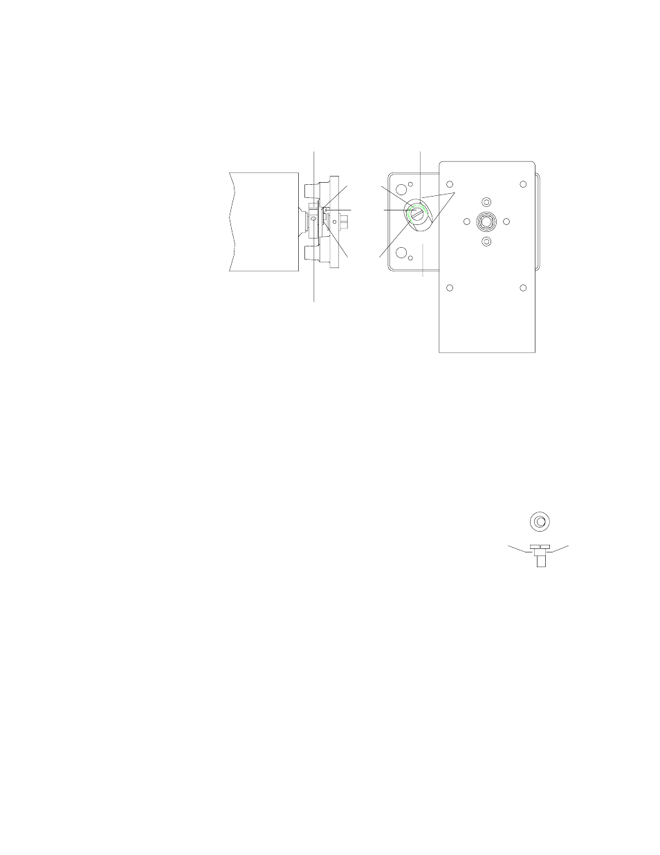
Temporarily install the mounting bracket at 90° from normal (see Figure 12)
so that the adjustment hole is accessible.
5.
Put the clamp ring back on and attach the valve or valve/standoff assembly.
Plug in the actuator power cord and align the valve as nearly as possible, as
described in Section 5.4, Alignment Procedure.
6.
Unplug the power cord.
7.
Use a 7/64 hex driver to loosen the 6-32 cap
screw on the gearshaft crank. (Figure 14)
8.
Use a screwdriver to
slightly
move the gearshaft
crank pin. (Figure 15) To
increase
the stroke,
rotate it slightly (1/16 turn) in the direction which
has the most resistance. To
decrease
the stroke,
rotate it in the direction which has the least resis-
tance.
9.
Lock the 6-32 cap screw on the gearshaft.
10. Plug in the power cord. Cycle the valve several times and check the
alignment. If the valve rotation is still incorrect, loosen the gear shaft crank
screw and readjust the gear shaft crank pin to set rotation correctly.
11. When the rotation is correct, unplug the power cord and reassemble the
electric actuator and valve with all the parts in proper orientation.
12. Realign the valve as described in Section 5.4, Alignment Procedure.
GEARSHAFT
CROSS-
LINK
END OF GEARSHAFT CRANK
GEAR-
SHAFT
CRANK
PIN
NYLON
WASHER
6x32 LOCKING CAP SCREW
FRONT OF
ELECTRIC
ACTUATOR
(Installed 90°
from usual
position)
FRONT OF
BRACKET
BOTTOM OF
ELECTRIC
ACTUATOR
(With bracket
removed)
ADJUSTMENT
HOLE
Figure 14: Actuator stroke adjustment
BOTTOM VIEW
SIDE VIEW
MAXIMUM
EDGE
MINIMUM
EDGE
Figure 15:
Gearshaft crank pin
15