3 installation of a valve with a standoff, Figure 9: valve on actuator with a standoff 9 – VICI Two position Standard electric User Manual
Page 11
coupling on the square driver of the actuator first. However, make sure that
the driver doesn’t get cocked.) The CR41/closemount standoff should end
up flush against the CR4/clamp ring.
5.
Tighten the HWSC-SC6-8B/screw (6-32 x 5/8") in the clamp ring with a
7/64 hex driver.
6.
Align the valve and actuator according to the Alignment Procedure found
in Section 5.4.
CAUTION: If the valve and actuator are not properly aligned, the slots
on the valve rotor and the ports in the valve body will not align properly.
The flow of sample may be blocked, and other problems may result.
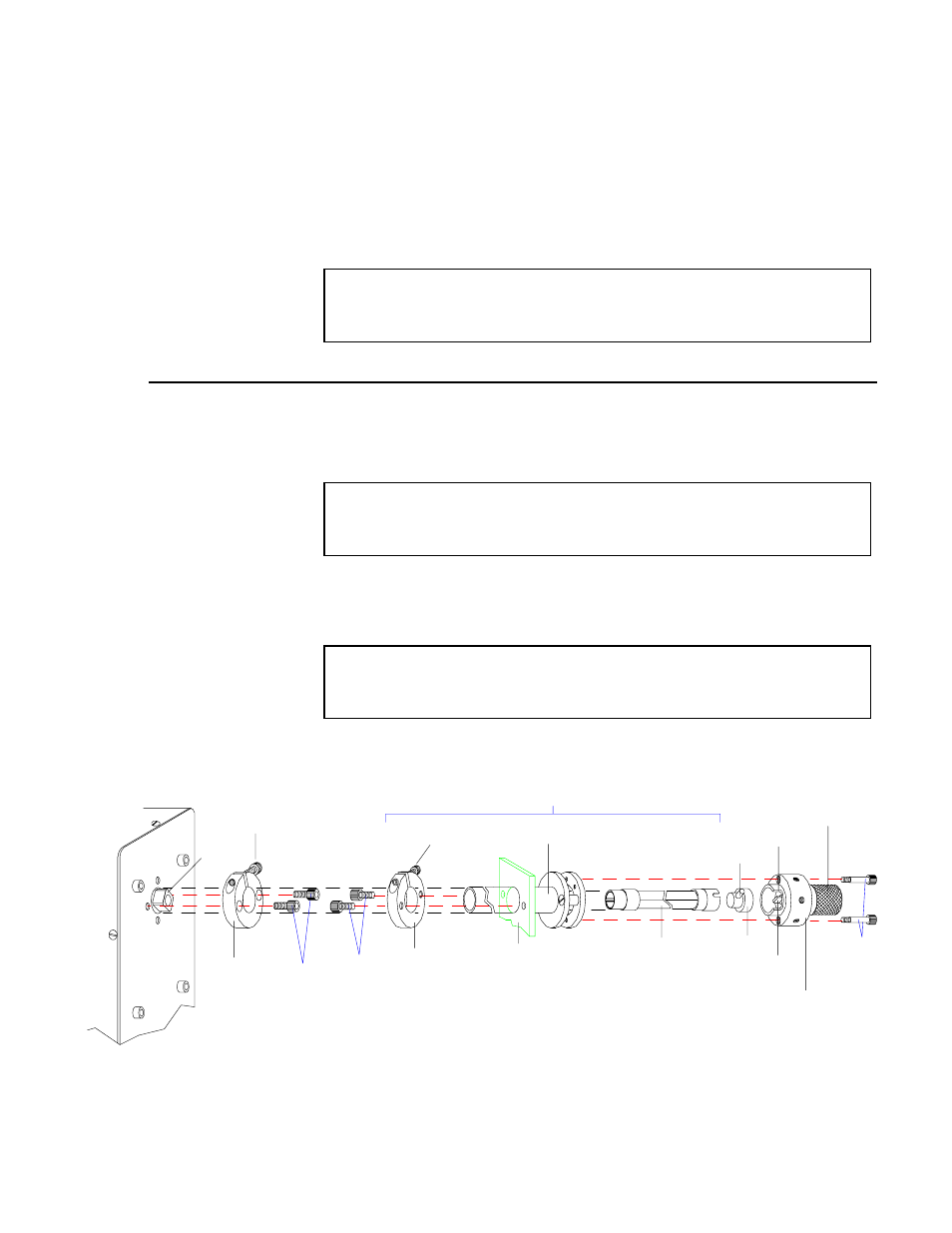
4.3 Installation of a Valve With a Standoff
If the electric actuator has been specified for use with a standoff, it will arrive from
the factory with the CR3/clamp ring already on the actuator. The clamp ring is
attached to the actuator with two HWSC-SC8-8B/socket head screws (8-32 x 1/2").
CAUTION: Do not use screws longer than 1/2" to attach clamp rings to
electric actuators. They will interfere with internal moving parts and
damage the actuator.
1.
Plug in the electric actuator and put it into the LOAD position (indicated by a
red light in the LOAD position) on the control box. The valve will have been
rotated to the counterclockwise position before the knob or the handle was
removed, so they should now be in the same relative rotational position.
CAUTION: The valve and the actuator must be in corresponding
rotational positions before assembly. If they are not, the valve or elec-
tric actuator may be damaged when operated.
HWSC-SC6-
10NT/
PRE-LOAD
ASSEMBLY
CUTOUT
ROTOR
PIN
ROTOR
TAB
VALVE
BODY
WD/DRIVER
STANDOFF
DRIVE SHAFT
STANDOFF ASSEMBLY (Lengths vary)
STANDOFF
OPTIONAL
MOUNTING
BRACKET
OR OVEN WALL
HWSC-SC6-8B/
SCREW
CR2/
CLAMP
RING
HWSC-SC8-8B/
SCREWS
SCREWS
(NOT
PRO-
HWSC-SC8-8B/
SCREW
SQUARE
DRIVER
CR3
CLAMP
RING
Figure 9: Valve on actuator with a standoff
9