VICI 450 Dynacalibrator User Manual
Page 6
2
Introduction
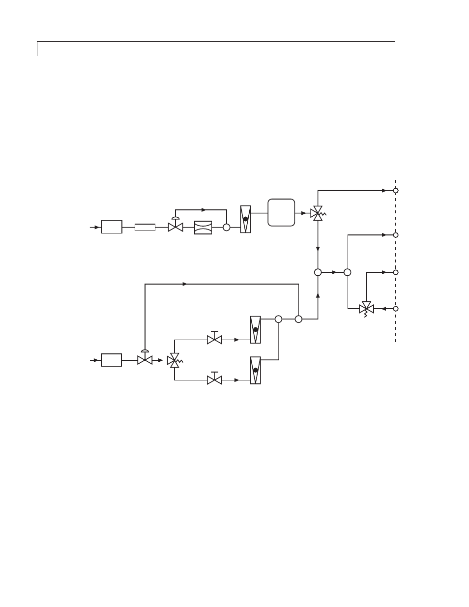
As indicated in Figure 1, the carrier stream passes through scrubber #1 and
micron line filter LF1 to the differential pres sure regulator DPR1. The scrubber
contains spe cially-activated charcoal designed for broad-based scrubbing action.
This scrubbing medium is particularly effective in removing sulfur dioxide and
other sulfur compounds.
The differential pressure regulator and carrier flow restrictor FR1 together
provide a highly stable carrier stream flow rate to the permeation chamber.
The standard carrier flow restrictor consists of a disk with a 0.006-inch diameter
orifice. The flow rate through the orifice is a function of the pressure differential
across it and this differential is maintained at 3.2 psi by DPR1.
SAMPLE
INLET
DILUTION
STREAM
INPUT
TEE
TEE
MIXING
TEE
OVERFLOW
VENT
CARRIER
STREAM
INPUT
SCRUBBER
#1
SCRUBBER
#2
LINE FILTER
LF1
DIFFERENTIAL
PRESSURE
REGULATOR
DPR1
CARRIER
FLOW
RESTRICTOR
FR1
PERMEATION
CHAMBER
CHAMBER
FLOWMETER
FM1
SPAN 1
FLOWMETER
FM2
TEE
DIFFERENTIAL
PRESSURE
REGULATOR
DPR2
SPAN 1 FLOW
CONTROL VALVE
FCV2
SOLENOID
CONTROL
VALVE
SV2
CHAMBER
VENT
SPAN 2
FLOWMETER
FM3
NO
NC
C
NO
NC
C
SPAN 2 FLOW
CONTROL VALVE
FCV3
SOLENOID
CONTROL
VALVE
SV1
TEE
NO
NC
C
SOLENOID
CONTROL
VALVE
SV3
STREAM
OUTLET
Figure 1: Model 450 plumbing schematic
The output of the permeation chamber is fed to solenoid control valve SV2.
When the front panel mode selector switch is in either the SPAN 1 or SPAN 2
position, the chamber output is routed through the valve from its C to its NC port
and to the mixing tee, where the calibrated dilution stream is added and mixed
into it to set the final concentration. When the front panel mode selector switch
is at STANDBY, ZERO, or REMOTE, SV2 is de-energized and the chamber output
passes through its C and its NO ports to the chamber vent. The dilution stream
alone then passes through the mixing tee.
The output of the mixing tee is split by another tee and fed to the overflow vent
and solenoid control valve SV3. When the front panel mode selector switch is in
either the STANDBY or REMOTE position with no remote inputs, SV3 blocks the
stream and causes it to be dumped to the rear panel overflow vent. The analyz-
er’s input is routed through the rear panel sample input port, the NO-to-C ports
of SV3, and the rear panel stream outlet.