Configuration 2, Configuration 3, Configuration 4 – VICI 450 Dynacalibrator User Manual
Page 33
29
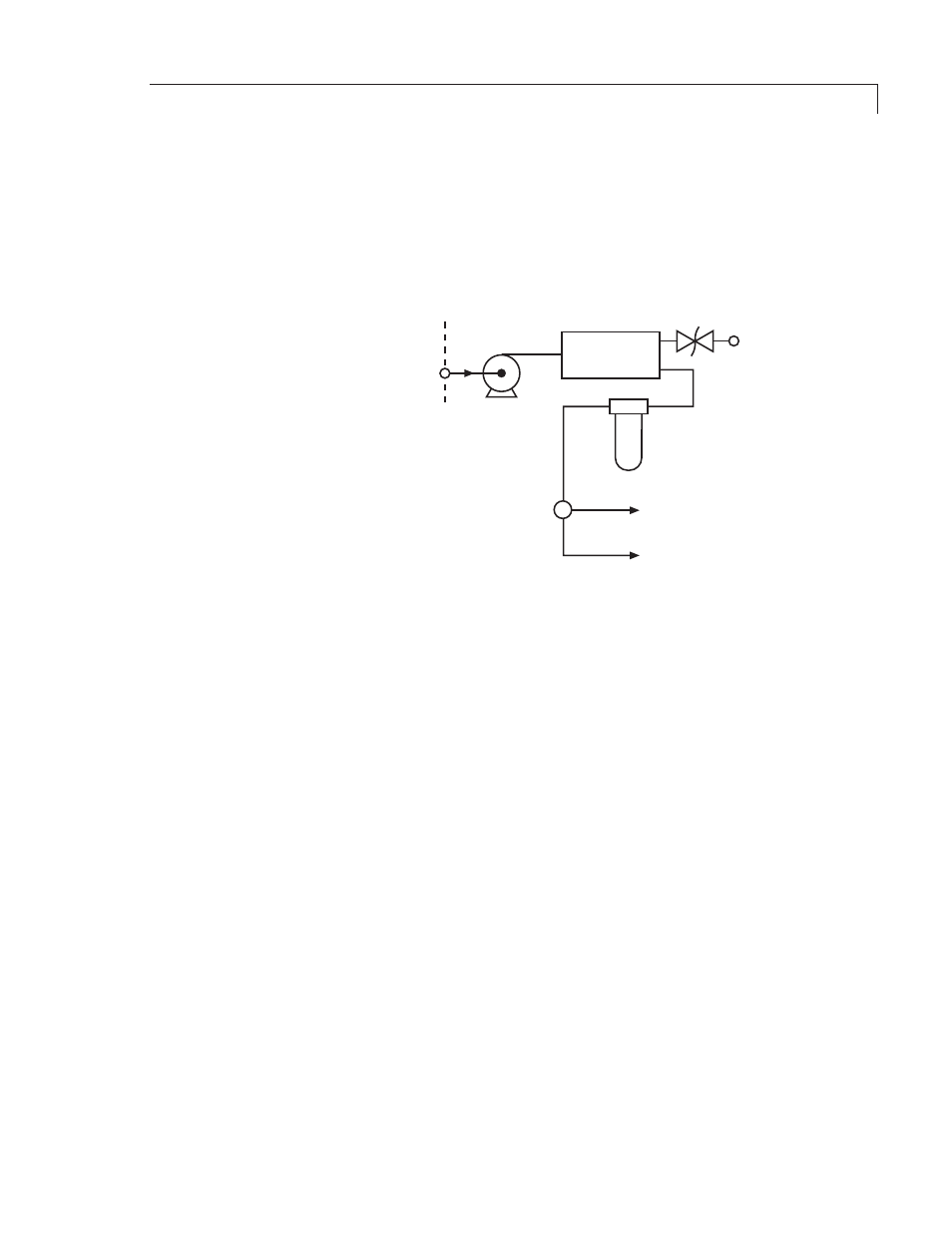
Configuration 2
Pump P1 (Figure 11) draws gas in through the supply inlet on the back panel
and delivers it to accumulator AC1. The accumulator smooths out pressure puls-
es, with the back pressure regulator providing continuous pressure regulation
to cover the dynamic range required. The output of the accumulator is passed
through filter F1, and split by the tee into carrier and dilution streams.
SUPPLY
INLET
DILUTION
STREAM
CARRIER
STREAM
FILTER
F1
TEE
MAIN PUMP
P1
ACCUMULATOR
AC1
BACK PRESSURE
REGULATOR
BPR1
Configuration 3
In this configuration (Figure 12), Pump P1 draws gas in through the supply inlet
on the back panel and delivers it to accumulator AC1. The accumulator smooths
out pressure pulses, with the back pressure regulator providing continuous
pressure regulation to cover the dynamic range required. The output of the
accumulator is passed through filter F1, with a tee at the filter output splitting
the supply into carrier and dilution streams. The carrier stream is plumbed to
the carrier outlet on the back panel, which must be plugged if an external carrier
supply is used. This port can be connected through external scrubbing media
(filters, driers, etc.) or simply looped to the carrier inlet port. Filter F2 removes
particulates from the carrier stream. The dilution stream output of the tee is
simply passed through filter F1.
Configuration 4
Input configuration 4 is shown in Figure 13. Pump P1 draws gas in through the
supply inlet on the back panel and delivers it to accumulator AC1. The accumu-
lator smooths out pressure pulses, with the back pressure regulator providing
continuous pressure regulation to cover the dynamic range required. The output
of the accumulator is passed through filter F2, with a tee at the filter output split-
ting the supply into carrier and dilution streams. The dilution stream is plumbed
to the back panel dilution outlet, which must be plugged if an external dilution
supply is used. This port can be connected through external scrubbing media
(filters, driers, etc.) or simply looped to the dilution inlet port. Filter F1 removes
particulates from the dilution stream. The carrier stream output of the tee is
passed through filter F2.
Advanced Theory of Operation
Figure 11: Diagram of configuration 2