Configuration 5 – VICI 450 Dynacalibrator User Manual
Page 35
31
Configuration 5
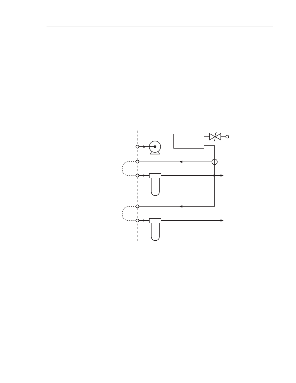
in this configuration (Figure 14), pump P1 draws gas in through the supply
inlet on the back panel and delivers it to accumulator AC1. The accumulator
smooths out pressure pulses, with the back pressure regulator providing
continuous pressure regulation to cover the dynamic range required. A tee at
the output of the accumulator splits the supply into carrier and dilution streams,
each of which is plumbed to a back-panel outlet port which must be plugged if
an external supply is used. These ports can be connected individually through
external scrubbing media (filters, driers, etc.) or simply looped to their respective
inlet ports. Filters F1 and F2 remove particulates from these two streams.
SUPPLY
INLET
DILUTION
STREAM
CARRIER
STREAM
TEE
MAIN PUMP
P1
ACCUMULATOR
AC1
BACK PRESSURE
REGULATOR
BPR1
FILTER
F1
DILUTION
OUTLET
DILUTION
INLET
BYPASS
LOOP
FILTER
F2
CARRIER
OUTLET
CARRIER
INLET
BYPASS
LOOP
Figure 14: Diagram of configuration 5
Advanced Theory of Operation