VICI 450 Dynacalibrator User Manual
Page 19
15
Metronics Inc.
SHUTDOWN
30°
120°
.15
.10
.05
CHAMBER
FLOW
MODE CONTROL
REMOTE
SPAN 1
ZERO
DYNACALIBRATOR
MODEL 450
PERMEATION CHAMBER
LOCK
TEMPERATURE °C
PNL TMP
SET
4A
6A
MAIN
HEATER
DILUTION
FLOW
CONTROLS
PERMEATION CHAMBER
SPAN 2
STANDBY
READ
SPAN 2
FLOW
READ
SPAN 1
FLOW
SPAN 1
DILUTION
FLOWMETER
MODE
SELECTOR
MODE
INDICATORS
SPAN 2
DILUTION
FLOWMETER
HEATER
CIRCUIT
BREAKER
MAIN
CIRCUIT
BREAKER
HEATER
POWER
SWITCH
HEATER
INDICATOR
SPAN 2 (left) and
SPAN 1 (right) DILUTION
FLOW CONTROL VALVES
MAIN
POWER
INDICATOR
MAIN
POWER
SWITCH
PERMEATION
CHAMBER
CHAMBER
FLOWMETER
TEMPERATURE
DISPLAY
OVER TEMPERATURE
LIMIT THERMOSTAT
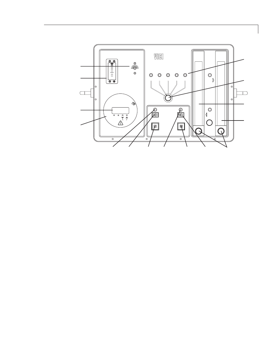
Figure 7: Model 450 front panel controls and indicators
MODE SELECTOR switch and indicators
The five position switch selects the calibration mode. LEDs indicate the selected
mode.
• STANDBY: The permeation chamber output is dumped out the chamber vent,
the dilution stream exits through the overflow vent, and sample input is fed
through the unit from the sample inlet to the stream outlet and on to the
analyzer.
• ZERO: The permeation chamber output is dumped out the chamber vent.
Sample input is blocked; the dilution stream is fed through the SPAN 1 flow-
meter and out the stream outlet to the analyzer.
• SPAN 1: With the sample input blocked, the chamber output and the dilution
stream through the SPAN 1 flowmeter are mixed and fed through the stream
outlet to the analyzer for low concentration calibration.
• SPAN 2: With the sample input blocked, the chamber output and the dilution
stream through the SPAN 2 flowmeter are mixed and fed through the stream
outlet to the analyzer for low concentration calibration.
• REMOTE - Unit defaults to the STANDBY mode. Remote contact closures
between rear-panel terminals C, V1, V2, and V3 place the unit in ZERO, SPAN 1,
or SPAN 2 mode, respectively.
Getting Started