Tweco 9-9385 User Manual
Page 2
June 23, 2011
2
Manual 0-5059_AB
B. Cover Installation
1. Reverse previous procedures for cover installa-
tion.
NOTE
When installing the upper screws, attempt to reuse
the original threads. The easaiest way to do this
is by turning the screw counter-clockwise until
you feel the threads lign up, then begin to turn the
screw clockwise to tighten. Do not over tighten.
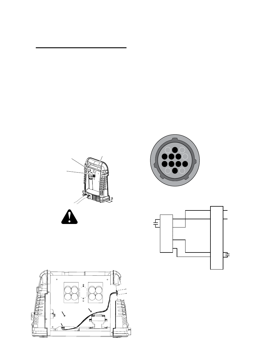
C. Automation Harness Installation
1. Remove the metal plate covering the two access
holes in the rear panel. You can save this for con-
verting back to just a manual system or discard
if you have no intensions of doing so.
2. Using the two screws included in this kit, install
the CPC end of the interface cable harness con-
nector in the lower hole in the back of the power
supply. Tighten the hardware securely. Do not
overtighten.
Automation Interface
Cable Port
Filter Assembly
Input Power Selection
Art # A-08354
CAUTION
Do not overtighten these screws. Overtightening
could strip out the holes in the plastic flange sup-
porting the cable connector.
3. Route the harness behind the contactor and under
existing wiring. Connect the multi pin strip end
of the harness to J-10 on the Main PCB along the
bottom toward the front of the unit.
-V OUT 1
WORK 1
J10
-V OUT 1
WORK 1
Art # A-08357
4. If not using a height sensing device skip to the
next step. If using a customer supplied auto
voltage sensing device for height control, the
wires will need to be fitted with a proper size
ring terminal. Feed those wires through the top
hole in the rear panel. Use an M4 .7x8mm screw
to secure the negative wire to the main PCB at "-V
out 1" above the terminal strip just done. Remove
the screw securing the Work Lead to "Work 1" and
attach the positive wire to this same terminal with
the Work Lead. Secure these wires to the rear
panel with a proper sized Hayco type through
hole protector.
5. If not using a height sensing device just snap the
included plug into the top hole of the rear panel
from the rear.
6. Harness pin-out is as shown in the following il-
lustrations.
Art # A-08356
1
4
12
14
3
3 & 4 - START/STOP
23x5291
12 & 14 -
OK-TO-MOVE,
DRY CONTACT
}
BASIC CNC INTERFACE OPTION
J2
2
3
4
5
6
7
8
9
10
11
12
13
14
1
P10
1
2
3
4
5
6
7
8
Art # A-08387
OK To
Move
5A at
250VAC
or 30VDC
OK TO MOVE
/START / STOP
+
-
If using a
switch, it
must withstand
12VDC at 50mA
This completes the installation of the Automation Kit.
NOTE
Every effort has been made to provide com-
plete and accurate information in this manual.
However, the publisher does not assume and
hereby disclaims any liability to any party
for any loss or damage caused by errors or
omissions in this Manual, whether such er-
rors result from negligence, accident, or any
other cause.