Tweco 7-3448 User Manual
Page 2
©2000 Thermal Dynamics Corp., Printed in USA
2
Manual 0-2829 Dated 5/12/00
used and need to be taped out of the way to
prevent contacting the Negative/Plasma or
Pilot Leads.
9. Tighten the Strain Relief onto the Torch Leads.
10. Reinstall any covers removed (see WARNING).
11. Install the proper torch consumables for the Power
Supply amperage.
12. Reconnect main input power to the Power Sup-
ply and turn the unit ON.
13. Set air pressure to 60 - 70 psi (4.1 - 4.8 bar).
14. Test torch for proper operation
B. Mechanized Systems With Shielded Leads
1. Turn OFF the power supply.
2. Disconnect the main input power to the power sup-
ply.
3. Remove the existing torch and strain relief from
the power supply, removing covers as required.
4. On the RPT Torch remove the retaining nut from
the Strain Relief.
5. The Control Connector Plug must be installed per
the following:
a. Connect the Control Connector Plug to the
Power Supply.
b. Inside the Power Supply Bulkhead area, route
the Remote Control Connector end of the Con-
trol Connector Plug through the Strain Relief
Nut.
c. Continue routing the connector out the hole in
the front of the Power Supply.
d. Feed the end of the torch lead and the Strain
Relief into the hole in the unit while routing
the single black wire into the notch of the Strain
Relief.
e. Tighten the Strain Relief Nut to secure the Strain
Relief to the Power Supply.
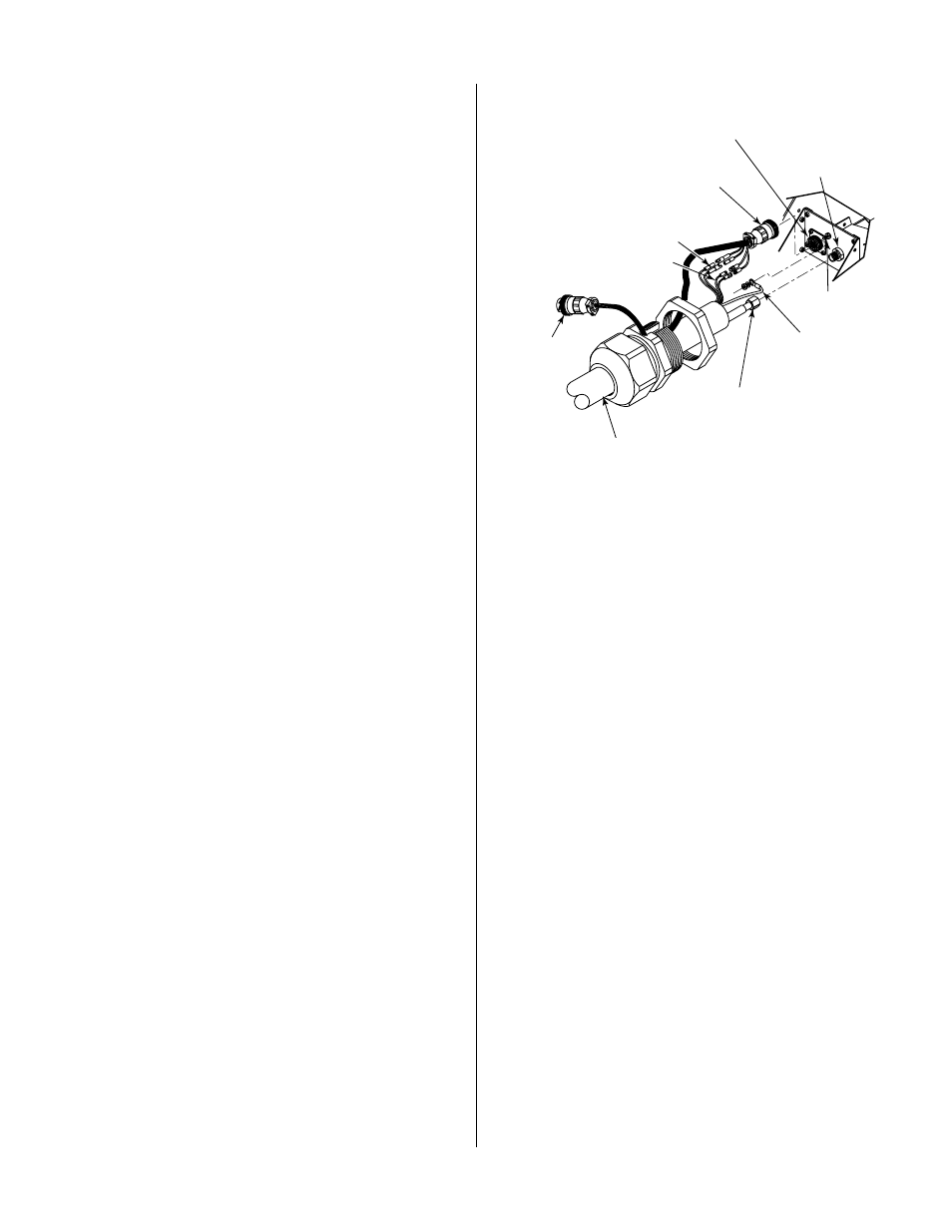
Pilot Lead
Torch Lead
Assembly
Negative/Plasma
Lead
Control Connector
Pilot Lead
Stud
Negative/Plasma
Lead Connection
A-02844
Control (PIP) Circuit
Connectors
Shield Connectors
Control Connector
Plug
Remote
Cable
Connector
6. Connect the pilot wire (+) from the replacement
torch to the Power Supply and tighten securely.
7. Connect the Negative/Plasma Lead from the re-
placement torch to the Power Supply. Slide the
protective boot over the lead connection.
8. Connect the Control (PIP) and Shield Connectors
to the mating connectors on the Control Connec-
tor Plug.
9. Tighten the Strain Relief onto the Torch Leads.
10. Reinstall any covers removed (see WARNING).
11. Install the proper torch consumables for the Power
Supply amperage.
12. Reconnect main input power to the Power Sup-
ply and turn the unit ON.
13. Set air pressure to 60 - 70 psi (4.1 - 4.8 bar).
14. Test torch for proper operation
NOTE
Every effort has been made to provide com-
plete and accurate information in this manual.
However, the publisher does not assume and
hereby disclaims any liability to any party for
any loss or damage caused by errors or omis-
sions in this manual, whether such errors re-
sult from negligence, accident or any other
cause.