Triton BRA 100 User Manual
Page 4
6
7
GB
GB
Fit a Pivot Bracket (D) and Pointer Bracket (E)
to the topside of each Track Arm (B &C) and
a Track Plate (F)to the underside. Fasten into
place using Countersunk Screws (G) and Flange
Nuts (H). The locations of the pivot brackets are
shown alongside the scales. Fasten the track
arms to the front and rear quadrants, using
Mushroom Head Screws (I), Nyloc Nuts (J),
Coach Bolts (K) and Round Knobs (L). Do not
over-tighten the nyloc nuts as the quadrants
must be free to pivot smoothly.
Fitting to the compact
Unplug the saw, and make sure the switch is
‘Off’. Remove the rip fence and overhead guard,
but leave the guard support in place.
Make sure
the blade is at full height and square to the
table.
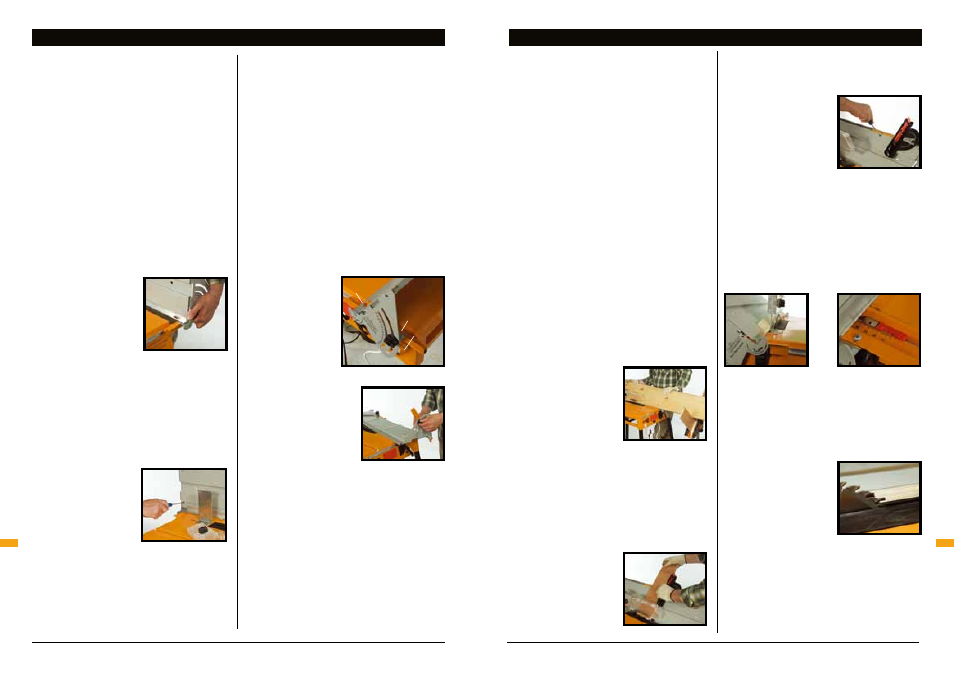
Set the Bevel Ripping Guide
at 90° and insert it into the
rip fence tracks from the
right (when viewed from
the switchbox end), as
shown in Fig. 2.
Loosen the countersunk screws and slide the
front edge support to a position approximately
5mm in front of the saw blade. If you have a
small saw (185 or 210mm) you will only use the
two inner holes to fasten the front edge support.
It will still be secure. If necessary adjust the
position of the rear edge support to just clear the
overhead guard support.
Place a straight edge
across the two edge
supports, as shown in
Fig. 3, to ensure they
are exactly in line, then
tighten the screws to
secure them in place.
Slide the bevel ripping guide in (still set at 90°)
until it touches the saw blade, front and rear.
Spin the blade backwards by hand. The teeth
should just touch the work panel (A). Check
whether you have identical readings on the
front and rear track arms, ie. that the guide is
exactly parallel to the blade and to the table. The
readings do not have to be ‘0’, but they should
be similar to each other. (A variation of 1mm is
acceptable.)
Take note of the scale readings, or mark them
with a scratch or pen mark, for reference when
re-fitting.
If variation is more than 1mm, turn the blade a
little and try again. A minor flatness problem in
the blade can become a significant scale error.
Check whether any mis-match is due to slight
sideways play at the back of the blade, and
check whether the saw is correctly mounted.
Refer to the compact manual if saw re-alignment
is required.
A secondary scale is printed on each track
arm, in case the main scales are obscured by
the front edge support or by sawdust in use.
Reference these
scales off the end
of aluminium fence
clamping strip as
shown in Fig. 4.
Again, the readings
front and rear don’t
have to be ‘0’, but
should
both agree (+/- 1mm or so).
The track arms must be
set at 90° for the
quadrants to be folded
behind the main panel for
compact storage. Fig. 5.
Safety warnings
Most bevel angles can be cut with the overhead
guard in place. If you need to remove the guard
for a specific cut, take great care. Replace the
overhead guard before continuing.
Always keep fingers well clear of the blade
and never push with fingers trailing behind the
workpiece near the blade. Ensure hands will be
safe even if they slip, or if the workpiece kicks.
Take care when handling workpieces and offcuts
as bevel cuts can have very sharp edges.
Stand on the right hand side of the compact,
hold the workpiece firmly down onto the front
edge support and against the work panel. As the
back of the workpiece passes off the front edge
support, take care to prevent it from dipping
down against the blade, as this will cause a slight
step in the bevel. This is particularly noticeable
with shorter pieces, because of their limited
contact with the edge supports.
By practising on scrap material, you will find the
best hand positions, and the best use of hold-
down pressure to avoid this final ‘dip’. Begin by
practising on medium sized pieces, and try using
the top of the work panel as a finger rest to help
control the workpiece throughout the cut.
Note: a perfect bevel requires the workpiece to
be flat, and to have a perfectly straight edge to
start with.
1. Wide workpieces
The maximum width of manageable workpiece
depends on the skill and experience of the
operator, and the weight of the material. As a
general rule, up to 600mm widths can be handled
comfortably. For larger
sizes you should have
someone assist you, or
set up infeed / outfeed
supports using the Triton
Multi-Stand(s), as in Fig. 6.
2. Long workpieces
When bevelling long workpieces, use Triton
Multi-Stand(s) to provide infeed and / or outfeed
support, or have someone assist you. Fig. 6.
3. Narrow workpieces
The compact protractor, inserted into the slot
along the top of the work
panel, can be used for
extra guidance and support
when bevel cutting narrow
workpieces across the
grain. See Fig. 7.
The protractor should slide smoothly, without
sidewards play along the full length of the slot.
If this is not the case loosen the Phillips-Head
screws and adjust the
width of the slot until the
protractor fits snugly,
then re-tighten. Fig. 8. If
necessary, spray the slot
with a spray lubricant, such
as RP7 or WD40, to improve
the protractor sliding action.
4. Chamfering
If you wish to chamfer an edge, rather than cut
a full bevel, unlock the bevel ripping guide and
move it away from the blade to the required
position. Both ends must be locked at the same
selected scale reading, ie. the guide must remain
exactly parallel to the blade, Fig. 9 & 10.
5. Fine work
To protect fragile work from splintering near the
end of the cut, loosen the Phillips-head screws
and move the front edge support closer to the
blade, as shown in Fig. 11. This will provide
greater infeed support. After any adjustment,
rotate the blade to ensure
the teeth clear the edge
support, then make sure the
screws are fully tightened.
Note: chamfers are not
possible in this position.
Remember to return the
front edge support to its
original position when finished.
Assembly
Operating
ASSEMBLY
OPERATING
Fig.2
Fig.3
Fig.4
Fig.5
Fig.6
Fig.7
Fig.8
Fig.9
Fig.10
Fig.11
Main
scale
Secondary
scale
Use this edge
as your datum