Gain - trim and fader relationship, Input trim input fader, High-pass filter – Sound Devices 552 User Manual
Page 20
552 User Guide and Technical Information
16
v. 1.4 Features and specifications are subject to change. Visit www.sounddevices.com for the latest documentation.
disabled, no voltage is applied to the microphone input. Do not apply power to ribbon microphones,
improperly wired cables can permanently damage the microphone.
Gain - Trim and Fader Relationship
The gain of an input is adjusted by two controls, Input Trim and Input Fader. This two-stage archi-
tecture is identical the to topology of mixing consoles and provides a great deal of flexibility. Input
Trim is often thought of as a course gain control and the Input Fader as the fine gain control.
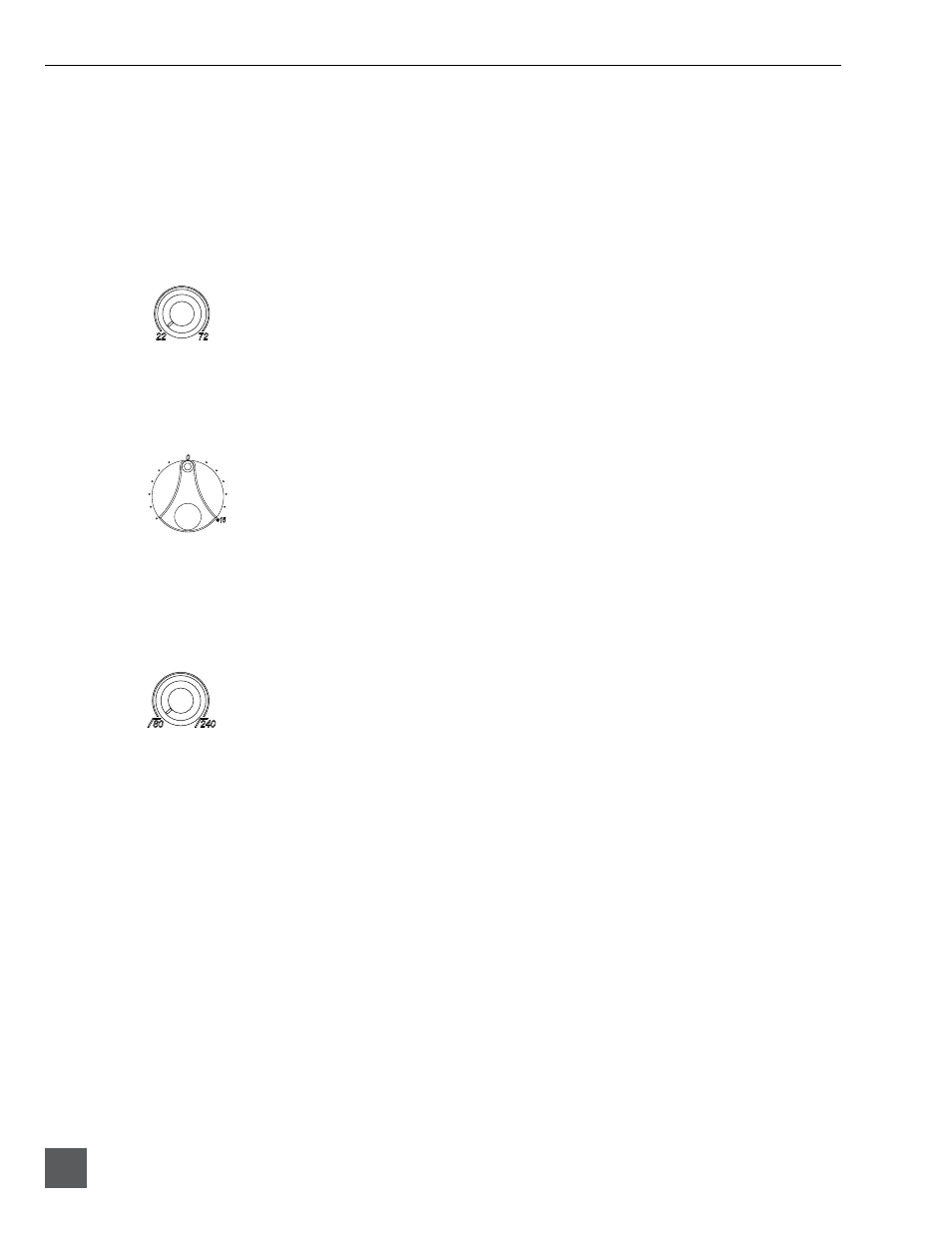
Input Trim
The 552’s input sensitivity is set with the pop-up knob Trim control. With the Input Fader set to unity
gain (0 dB or 12 o’clock), make the appropriate adjustments using the Trim control. Once the coarse
gain is set to the desired level, recess the Trim control to hide it from the 552’s mixing surface. Trim
level is adjustable from 22 to 72 dB of gain.
Input Fader
The Input Fader is the primary control used during mixing operation. Use the Input Fader to make
fine gain adjustments during operation. The fader can be attenuated from off (full counter-clockwise
position) to +15 dB above the set Trim level (full clockwise position). To optimize gain structure for
the best noise performance operate input faders at or near the 0 dB (unity gain) position.
High-Pass Filter
Each input channel has an adjustable high-pass filter controlled by the High-Pass Filter pop-up knob.
High-pass (or low-cut/low roll-off) filters are useful for removing excess low frequency energy from
audio signals. Wind noise is a common unwanted low frequency signal that can be reduced with
the use of a high-pass filter. For most audio applications engaging the high-pass filter is beneficial,
because audio information below 100 Hz is rarely used, especially for speech reproduction.
The 552’s high-pass filter circuit features an adjustable corner (-3 dB) frequency over a range from 80
to 240 Hz. Below 80 Hz, the filter’s slope is 12 dB/octave. At higher corner frequency settings, the
slope is 6 dB/octave.
See Specifications.
The purpose for this compound slope is to give additional
roll-off at the 80 Hz setting to reduce wind noise and low frequency rumble. The higher settings can
be used to counteract the proximity effect of directional microphones where a more gentle slope is
desired.
When engaged or disengaged, the high-pass filter gradually fades into the selected state. This pre-
vents sudden obvious pops in the audio.
The 552’s high-pass filter circuit is unique because of its placement before any electronic amplifica-
tion. Most mixer’s high-pass filter circuits are placed after the microphone preamplifier, such that all
of the low-frequency signals get amplified. By virtue of the 552’s circuit cutting the low-frequency
signals before amplification, higher headroom is achieved in the presence of signals with significant
low-frequency energy.