5 installation, 1 safety regulations, 2 installation of pump/unit – Richter RMA Series User Manual
Page 11: 3 alignment of pump-coupling-motor, 4 piping, 1 nominal size, Safety regulations, Installation of pump/unit, Alignment of pump-coupling-motor, Piping
Series RMA
Page 11
9475-050-en
Revision 12
TM 7978
Edition 08/2010
5
Installation
5.1 Safety regulations
Equipment which is operated in potentially
explosive areas must satisfy the explosion
protection regulations.
People with a pacemaker are at risk from the
strong magnetic field of the magnetic drive. It
may be life-threatening for them to stay at a
distance of less than 20” (500 mm) to the
pump.
5.2 Installation of pump/unit
The structural work must be prepared in accordance
with the dimensions in the installation drawing.
Method of installation: on a grouted base plate and
firm foundation
Align base plate on the ground foundation.
Insert foundation bolts and grout base plate.
Do not tighten the foundation bolts uniformly and
firmly until the mortar has set.
Other possibilities of installing the pump are:
4-point installation
4-point installation with base plate.
As soon as additional installations are
mounted, the stability of the entire unit
installed without a foundation must be
checked.
5.3 Alignment of pump-coupling-
motor
The following information is of a general
nature. If necessary, special notes of the
coupling and motor manufacturer are to be
observed.
After attachment of the base plate on the
foundation and connection of the pipes, the
alignment of the coupling must be carefully
checked and, if necessary, the unit re-aligned with the
motor.
A coupling check and possible re-alignment is also
necessary if the pump and motor are supplied on a
common base plate and aligned.
Prior to alignment undo the support bracket 183
and then tighten it without stress.
The pump is to be aligned in all directions using a
spirit level (on shaft/discharge nozzle) (admissible
position deviation max. 0.08” in/ft (0,2 mm/m).
A distance depending on the coupling used is to
be observed between the pump and motor shafts.
See installation drawing.
Use supports in the direct vicinity of the bolts
foundation/base plate.
Ensure that the unit cannot be started
during work without the coupling guard.
5.4 Piping
Before the pump is installed, both, the suction and
supply lines as well as the discharge line are to be
cleaned.
Dirt or damage to the sealing surfaces is best
avoided if the flange covers remain on the flanges
until just before installation.
Use flange gaskets suitable for the medium.
The screw tightening torques in Section 1.1 are to
be observed for tightening the flange screws.
5.4.1 Nominal size
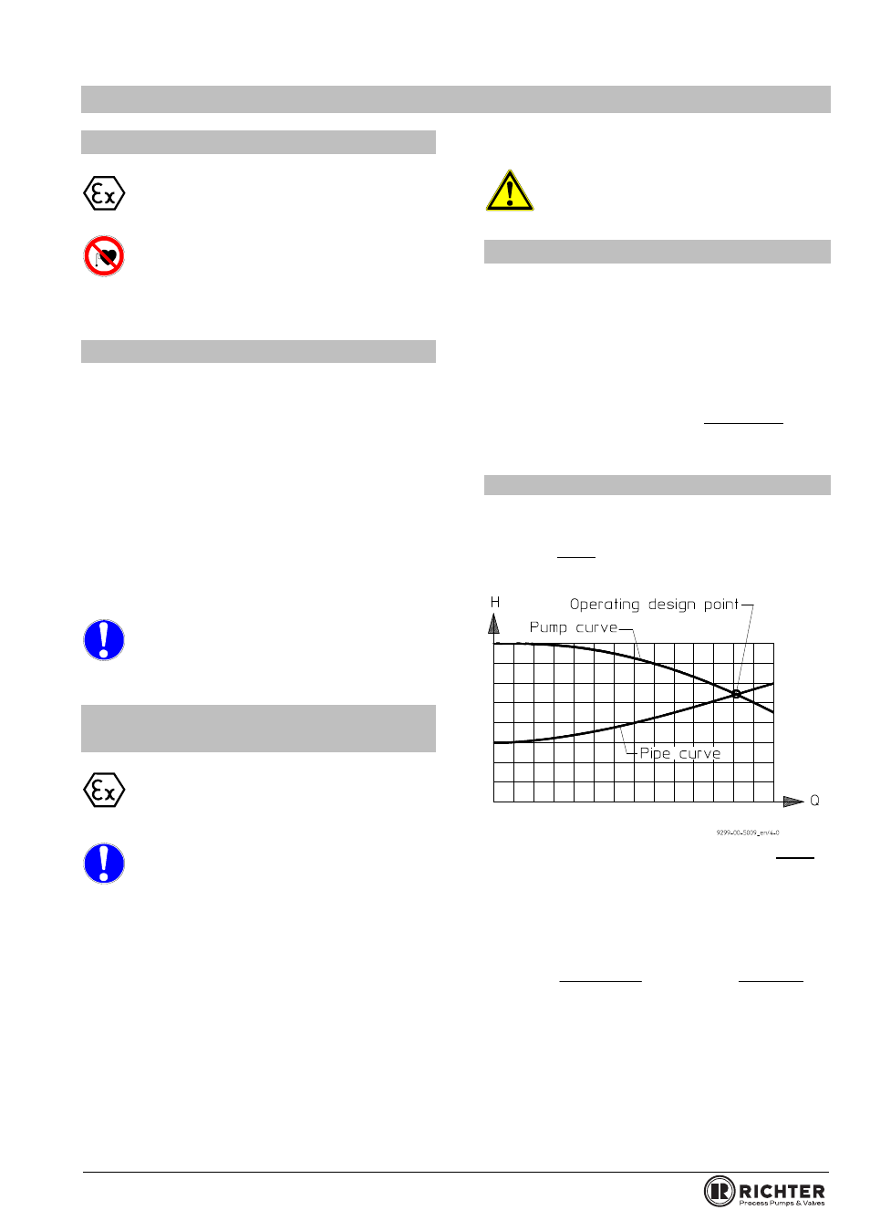
The operating design point of a centrifugal pump lies
at the intersection of the pump curve and the pipe
curve, see Fig. 2. The pump curve is provided by the
pump manufacturer. The pipe curve is determined
using diagrams or PC programs.
Fig. 2
Under no circumstances can the nominal size of the
piping be derived from the connected nominal size of
the pump.
The pipe nominal size can also be determined using
the flow rate as a rough guide.
)
ft
(
A
x
449
)
gpm
(
Q
)
s
/
ft
(
v
2
=
)
m
(
A
)
s
/
m
(
Q
)
s
/
m
(
v
2
3
=
The velocity in the suction line should not exceed
6.56 ft/s (2 m/s) and 16.4 ft/s (5 m/s) in the discharge
line.
When determining the suction line nominal size, the
NPSH value (net positive suction head) must also be
observed. The NPSHR value required for the pump
is specified in the data sheet.