RCBS Bullet Feeder - Rifle User Manual
Page 6
- 6 -
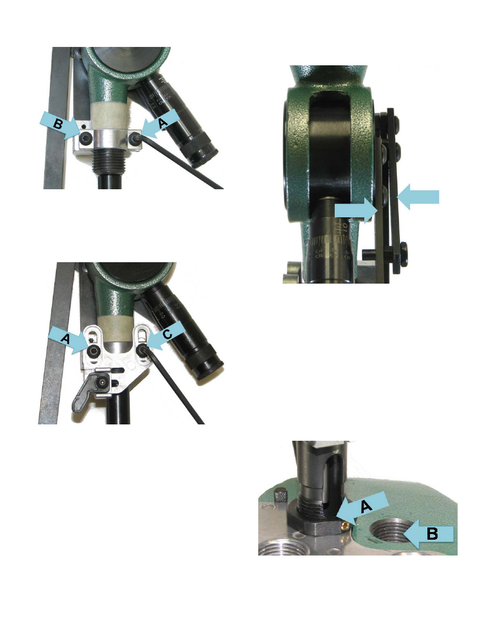
System found attached to the Powder Measure. Remove
the rear Button Head Cap Screw (B). See Photo 5.
Photo 5
Place Cam Plate Assembly onto upper Linkage Bracket
and secure the front with the 10-32x1½” BHCS found in
Parts Bag #1(C). Install the BHCS that was removed
from the front portion and use it to replace the rear 10-32
BHCS(A)
.
See photo 6.
Photo 6
Before tightening the two 10-32 BHCS, ensure that the
Linkage assembly is parallel to the powder measure
cylinder (see photo 7) and that it is back up to the tape
mark (photo 4). Tighten the two 10-32 BHCS;
adjustment of the Cam Plate will be covered later in this
section. The Cam Plate Assembly is now installed.
Photo 7
Re-install the Top Spring Anchor (B), Return Spring (A),
and Linkage Knob (C) (see Photo 3).
Install the Bullet Feed/Seat Assembly into a Die Plate at
the station immediately after the Powder Measure
station. The Die Body Feed-Thru Window bottom should
be positioned at the Lock Ring's top surface (A). The
Powder Measure Assembly was removed from station
“B” for clarity. See photo 8.
NOTE: You will be able to load cartridge lengths of 2.0 –
2.5 inches at this setting. For longer cartridges, raise the
Seater Assy as needed. For shorter cartridges, the
Seater Assy can be lowered until the Bullet Drop Tube
contacts the Lock Ring See ADJUSTMENT section.
Photo 8
Slide the Die Plate, with Bullet Feed/Seat Assembly
installed, into the press. This assembly must be oriented