Kenco Engineering KLCM User Manual
Page 3
OIL LEVEL CONTROLLER WITH
–17
(Waukesha VHP Engines F2895, F3251, F5108, L5790 & L7042),
-18
(-17 w/ meter),
-27
(for newer Waukesha engines same as –17),
–37
(Waukesha P9390),
-38
(same as –37 w/ meter),
-47
(Waukesha VGF L36 and P 48
Engines) and –FS OPTIONS
•
Remove the cast aluminum inspection door from the engine. Remove the clamp bar from the old door.
•
For –17, -18, -37, -38 install the o-ring into the groove of the Kenco door and replace the clamp bar on the back side of the door
using the 5/8” bolts and the stat-o-seals supplied by Kenco.
•
For –27, install the o-ring into the groove of the Kenco door and replace the clamp bar on the back side of the door using the
7/16” bolts and the stat-o-seals supplied by Kenco.
•
For –47, mount the inspection door with the bolts, seal washers, and gasket provided.
•
For –17, -27, -37, -38, place the controller assembly into the inspection port of the engine and tighten the center bolt(s) down.
•
Install the equalizing line between the controller cover plate and the door (Tubing and connectors supplied by Kenco).
•
Place the controller assembly into the inspection port of the engine and tighten the center bolt(s) down.
•
Install oil inlet line into the controller oil valve or the meter inlet port.
•
NOTE: For the –18 model, refer to the additional instructions supplied with the 1618 Kenco Low Flow meter.
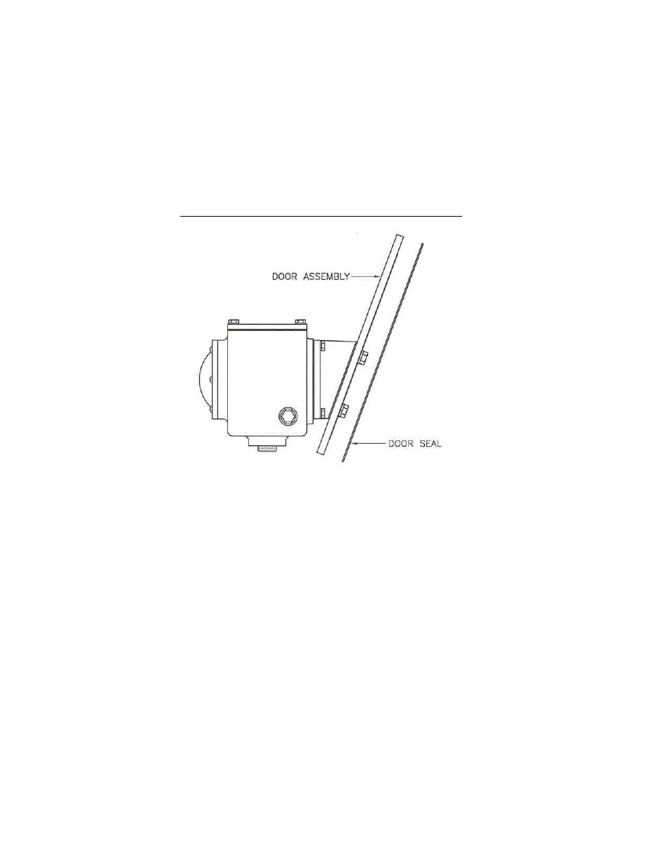
Figure 4: -Door Assembly for –17, -18, -27, -37, -38, -47
OIL LEVEL CONTROLLER WITH
-24
(Ariel Compressor JGB, JGE, JGH, JGK, JGR, JGT, JGV, & JGW) and
-48
(Ariel compressor JGC & JGD) AND –FS OPTIONS
•
Remove the sight glass located on the crankcase and replace it with the oil controller assembly using the mounting bolts and
gasket supplied with the unit.