Kenco Engineering KLCM User Manual
Page 2
OIL LEVEL CONTROLLERS WITH
–9
(Universal adapter),
-
10
(Slotted universal adapter),
-12
(Pole mounted adapter) AND –
FS OPTIONS
•
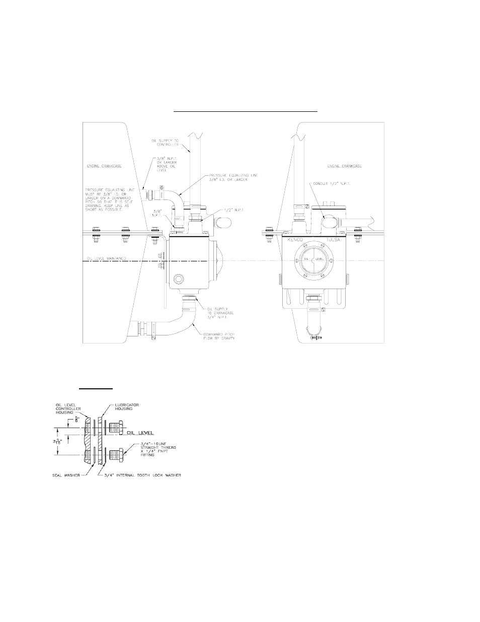
Set the controller so that the centerline of the sight window corresponds to the desired oil level in the crankcase.
•
Mount the controller close to the crankcase and connect the hose from the ¾” outlet located on the controller to the crankcase.
NOTE: The outlet port on the oil level controller must be located below the oil level in the crankcase.
•
An equalizing line must be used between the controller and crankcase in order to equalize the pressure. The tubing must be a
minimum of 1/2” I.D. and must be kept under 2 feet. DO NOT loop this line. It must be trap free and self draining, with a
downward pitch flow by gravity.
OIL LEVEL CONTROLLER WITH
–11
AND
–11-FS
OPTION (for Mechanical Lubricators): See Figure 3
OIL LEVEL CONTROLLER WITH
–14 AND –14 –FS
OPTION (White Compressor)
•
Remove the triangular blind flange located on the compressor and mount the controller assembly in its place.
• Drill holes in the lubricator housing as shown, and mount
the controller with the inlet located on the top side using the
seal washers and mounting bolts provided.
• Place the seal washers between the controller and the
lubricator housing.
Figure 3
Figure 2: Typical Mount of –9 Adapter