Figure 7: fire safe valve installation – Kenco Engineering 512 (old style) User Manual
Page 5
IV. INSTALLATION INSTRUCTIONS FOR FIRE SAFE VALVES (Patent No. 3,877,476): See Figure 7
NOTE: All lines between thermal valves, the supply tanks and the controller must be made of steel. DO NOT use rubber hose. The lines
should be ½” I.D.
•
The eutectic fuse element should always be in a downward position to help the element melt when heat is applied to the valve.
•
The 50-FS valve should be installed in the oil supply line as close to the controller as possible. Meters, filters and pressure regulators
should be installed between the controller and the 50-FS.
•
The 75-FS valve should be located as close to the crankcase as possible and the oil outlet line should be a minimum ¾” I.D. to
insure adequate oil flow to the crankcase.
NOTE: The 75-FS valve is not required when using –FS adapters other than –9 and –12.
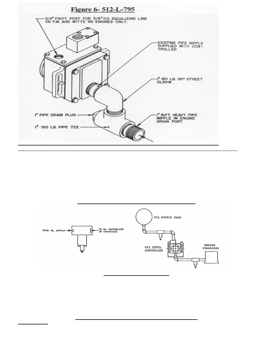
FIGURE 7: FIRE SAFE VALVE INSTALLATION
V. START-UP PROCEDURES
•
Flush the supply system and supply line with solvent to remove all burrs and construction debris.
•
Insure that the oil supply tank is full.
•
After the engine has been running for 1 hour, visually check the oil level in the sight glass. The oil level should be in the center of the
sight glass.
•
With the engine running, check the crankcase oil level. It should be the same as the oil level in the oil controller. If not, check the
installation of the equalizing line (if applicable) see instruction for the equalizing line at –9.
•
Check all piping connections for leaks and repair as needed.
VI .SIX MONTH SUGGESTED MAINTENANCE PLAN
Oil Valve Service
•
Close the oil supply valve and discount the oil inlet supply line.
•
Place a pan under the controller to catch the oil from the oil supply line.
•
Remove the inlet oil housing and clean the screen.
•
Once the screen is clean, reassemble and open the oil supply valve.
Note: Dispose of oil in a proper container.