Kenco Engineering 512 (old style) User Manual
Page 3
OIL LEVEL CONTROLLER WITH
–17
(Waukesha VHP Engines F2895, F3251, F5108, L5790 & L7042),
-18
(-17 w/ meter),
-27
(for
newer Waukesha engines same as –17),
–37
(Waukesha P9390),
-38
(same as –37 w/ meter),
-47
(Waukesha VGF L36 and P 48 Engines)
AND –FS OPTIONS
•
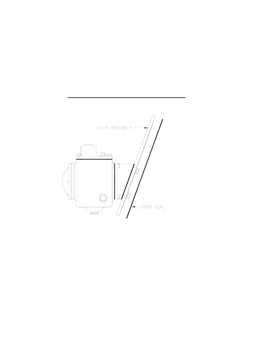
Remove the cast aluminum inspection door from the engine. Remove the clamp bar from the old door.
•
For –17, -18, -37, -38 install the o-ring into the groove of the Kenco door and replace the clamp bar on the back side of the door using
the 5/8”-11 bolts and the stat-o-seals supplied by Kenco.
•
For –27, install the o-ring into the groove of the Kenco door and replace the clamp bar on the back side of the door using the 7/16”
bolts, 7/16” flat washers and the fluorocarbon O-rings supplied by Kenco.
•
For –47, mount the inspection door with the bolts, seal washers, and gasket provided.
•
For –17, -27, -37, -38, place the controller assembly into the inspection port of the engine and tighten the center bolt(s) down.
•
Install oil inlet line into the controller oil valve or the meter inlet port.
•
NOTE: For the –18 model, refer to the additional instructions supplied with the 1618 Kenco Low Flow meter.
Figure 4: -Door Assembly for –17, -18, -27, -37, -38, -47
OIL LEVEL CONTROLLER WITH
-24
(Ariel Compressor JGB, JGE, JGH, JGK, JGR, JGT, JGV, & JGW) and
-48
(Ariel compressor JGC & JGD) AND –FS OPTIONS
•
Remove the sight glass located on the crankcase and replace it with the oil controller assembly using the mounting bolts and gasket
supplied with the unit.
OIL LEVEL CONTROLLER MODELS
512-A
(Arrow C46, C66, C106 and C245
), 512-FM
(, 512-W, AND 512-W98 AND FS
OPTIONS
•
Drain oil from the crankcase to a level below the oil gauge
Note: On Fairbanks Morse engines, oil draining can be facilitated by removing the coupling from the engine oil drain and installing a
pipe elbow on the nipple. Models ZC 118 and ZC 208 require ½” pipe and models ZC 346, 508, 739 require ¾” pipe. If a banded elbow is
used, it will be necessary to file off part of the gauge boss on some engines.
•
Remove all parts from the base oil gauge on the engine
•
Remove the adapter from the back of the 512 controller and bolt it in place of the base oil gauge
•
Mount the front of the controller with the oil inlet connection on top
•
Connect hose from the controller to the supply tank
Note: The hose should be self draining toward the controller and without restrictions. Clean any debris from the oil resevoir and hoses
before connecting to the controller.
•
On Fairbanks Morse and Witte 98 engines without an oil gauge, it will be necessary to use an equalizing line. See instruction for –9
adapter and refer to figure 4 for instructions.
Caution: Controller is made of cast aluminum. Overtightening may strip threads.
OIL LEVEL CONTROLLER MODEL
512-ML
AND FS OPTIONS
•
Drill holes in the oil controller mounting bracket to match the holes on the lubricator cover plate
•
Bolt in place making sure that the cap screws for mounting do not interfere with the lubricator operation
•
Connect the ½” pipe connection on the controller to a drain on the lubricator