Kenco Engineering Weld Pad Flat Glass Level Gauge User Manual
Page 2
Page 2
GAUGE CONSTRUCTION
WELDING INSTRUCTIONS
Weld Pad Gauges are shipped loosely assembled and should first be entirely dismantled. The pad may then be used as
a template for laying out the vision slot which is to be cut through the wall of the vessel. If internal welding is to be
performed (recommended), the width and length of the slot can be increased by chalking a second cutout line ¼” away
from the scribed line obtained in tracing the vision slot. This will provide a suitable shelf in which to lay the bead, as
shown in the following drawing
To avoid buckling, the pad should be tack welded at intervals, both internally and externally, in accordance with
recognized welding procedures, before placing the continuous welds. As an added precaution against distortion, the
welding pad gauge can be assembled without gaskets, using a steel spacer instead of the gasket-glass-cushion
assembly. This spacer can be cut from bar stock 1¼” X ¾”. The length will be determined by the length of the gasket
recess. This procedure will increase the rigidity of the pad and minimize the possibility of distorting the glass seating
surface.
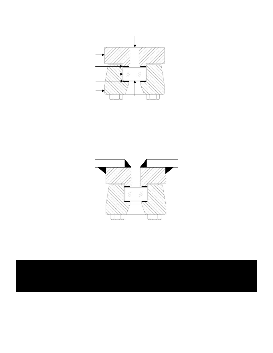
Weld Pad Gauge (Model KWR & KWT)
Gasket
Glass
Cushion
Cover
Glass
Reflex or Transparent
Chamber
Vessel Slot
CAUTION – Standard weld pad gauges will withstand loadings due to the pressure within the gauge itself, but
they are not designed to replace the vessel strength lost when the vessel wall is cut. Kenco has
no control over the loading which the vessel will impose on the pad. It is therefore impossible to
rate welding pad gauges. The vessel fabricator must provide suitable vessel wall reinforcement
to prevent the pad from being distorted during welding, or while under operating conditions.