Kenco Engineering KUST Switch User Manual
Page 4
TROUBLESHOOTING
Problem
Solution
Check wiring; verify that the correct input
voltage is applied
Verify that liquid is filling the sensor gap
Check for dense foam or dried product in
the gap. Switch may not function properly
if either condition exists.
Check sensor phono plugs for a good
connection. Unplug and Re-plug each
connection.
No output change with level change
Check for excessive aeration in process
fluid. This is particularly important in
viscous fluids.
Check wiring; verify that the correct input
voltage is applied
Check for turbulence. Relocate switch or
isolate from turbulence
The output is “chattering”
Check for excessive aeration in process
fluid. This is particularly important in
viscous fluids.
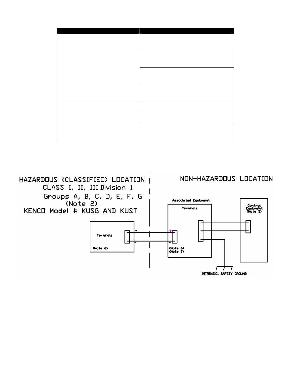
INTRINSICALLY SAFE CONTROL DRAWING
Entity Parameters:
Vmax = 36Vdc
Imax = 150mA
Ci = 0µF
Li = 54µH
NOTES:
1) Vmax > Voc; Imax > Isc; Ci + Ccable < Ca; Li + Lcable < La
2) Dust-tight conduit seal must be used when installed in Class II and Class III environments.
3) Control equipment connected to barrier must not use or generate more than 250V.
4) Installation should be in accordance with the CEC, Part 1.
5) No revision to drawing without prior CSA approval.
6) Associated equipment must be CSA Certified.
7) Associated equipment manufacturer’s installation drawing must be followed when installing this equipment.
8) For wiring refer to installation / operation manual.