Kenco Engineering KUST Switch User Manual
Page 3
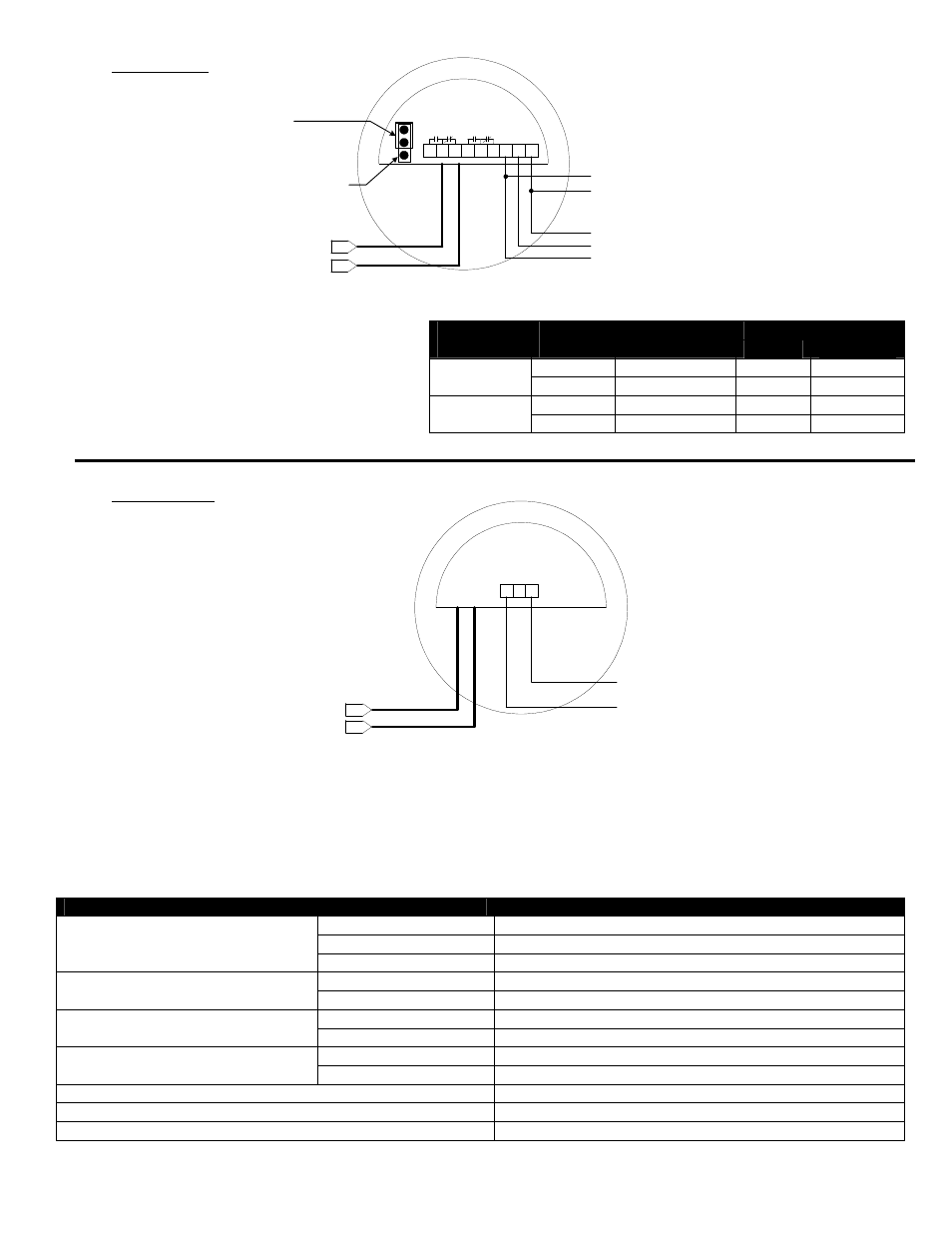
Relay Version
1. Connect power wiring
a. AC – Hot (L2), Neutral (L2),
and Ground (G)
b. DC – Positive (L1), Negative (G)
2. Connect relay wiring (see diagram)
3. Adjust failsafe jumper
a. HLFS – top (2) pins
b. LLFS – bottom (2) pins
2-Wire Version
1. Connect the power wires as shown in the diagram.
2. Measure the current in the positive lead
a. Dry = 4.0mA
b. Wet = 20.0mA
Specifications
Description
Specification
AC
115Vac or 230Vac; 50/60Hz
DC
12 or 24Vdc
Input Power
DC (Two-Wire)
9-30Vdc
Relay
10A DPDT
Output
Two-wire (Isolated)
4mA = Dry; 20mA = Wet
Switch
-20°F to 170°F
Temperature Range
Sensor
-40°F to 300°F
316SS
Vacuum to 1000psig
Pressure Range
Tefzel
®
Vacuum to 100psig
Sensitivity (Signal-to-noise Ratio)
500:1
Repeatability
±2mm
Response Time (on Alarm)
0.5 sec. non-adjustable
Relay Terminals
Media
Level
Fail Safe
Setting
Relay
Condition
NC to C
NO to C
HLFS
De-Energized
Closed
Open
Above
Setpoint
LLFS
Energized
Open
Closed
HLFS
Energized
Open
Closed
Below
Setpoint
LLFS
De-Energized
Closed
Open
G
L2
L1
NC
C
NO
NC
C
NO
}
115Vac or 230Vac
50/60 Hz
}
12 or 24Vdc
+
-
{
Coaxial Cable
To Sensor
Jumper
High Level Failsafe
(HLFS)
Low Level Failsafe
(LLFS)
-
+
}
{
9-30Vdc
Coaxial Cable
To Sensor
4 or 20mA