Kenco Engineering KUSG Switch User Manual
Page 3
Wiring
It is recommended that conduit be installed onto the ¾” NPT connection on the electronics housing. A seal drain fitting
should be used to prevent moisture from entering the switch. All wiring, conduit, and electrical fittings must conform to
local electrical codes for the location selected. If the switch is to be used in a Hazardous Area, the applicable codes of the
National Electrical Code must be followed as well.
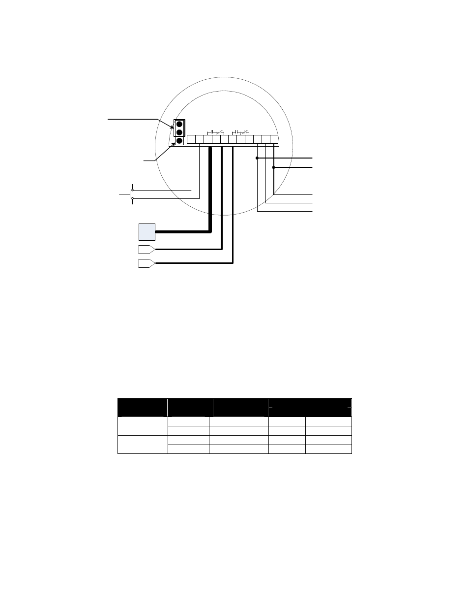
1. Connect power wiring
a. AC – Hot (L2), Neutral (L2), and Ground (G)
b. DC – Positive (L1), Negative (G)
2. Connect relay wiring (see diagram)
3. Connect Manual Self-Test terminals to a remote pushbutton (maximum distance 30 feet).
4. Adjust failsafe jumper
a. HLFS – top (2) pins
b. LLFS – bottom (2) pins
The following table shows the relay condition for each switch state:
Relay Terminals
Media
Level
Fail Safe
Setting
Relay
Condition
NC to C
NO to C
HLFS
De-Energized
Closed
Open
Above
Setpoint
LLFS
Energized
Open
Closed
HLFS
Energized
Open
Closed
Below
Setpoint
LLFS
De-Energized
Closed
Open
+
G
L2
L1
NC
C
NO
NC
C
NO
-
Jumper
High Level Failsafe
(HLFS)
Low Level Failsafe
(LLFS)
}
115Vac or 230Vac
50/60 Hz
}
12 or 24Vdc
+
-
{
Molex Conn. &
Coaxial Cable
To Sensor
Manual Self-Test
Maximum Wiring
Distance - 30ft.