6 rear panel connectors english – HK Audio FirNet Manual User Manual
Page 9
9
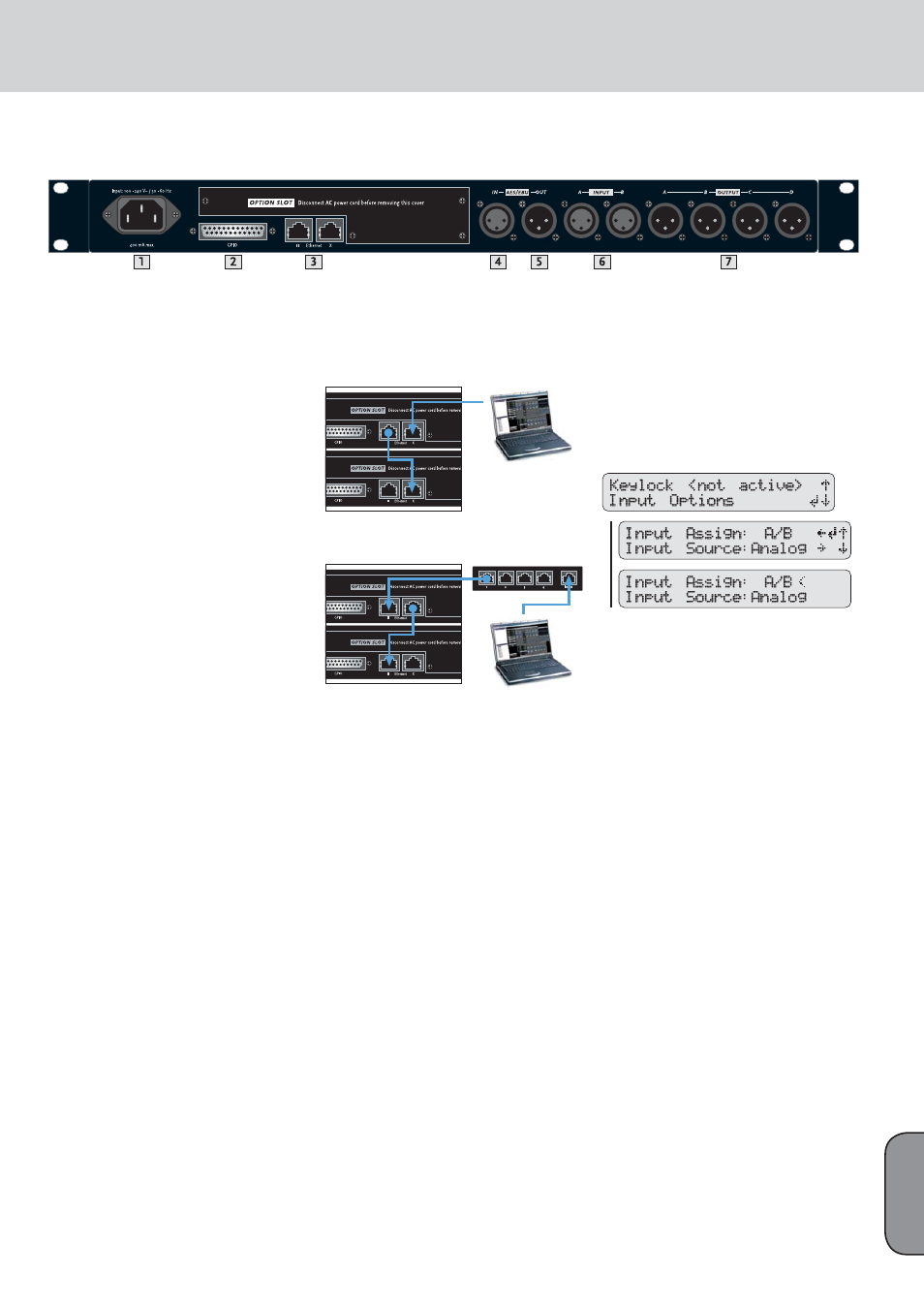
1 100-240 V~ / 50-60 Hz Mains
This three-pole non-heating equipment connector
with a ground contact connects the FIRNET control-
ler to the mains power supply. The multi-voltage po-
wer supply unit allows the controller to be connec-
ted directly to all mains voltages ranging between
100 V and 240 V without requiring transformers
and the like. Its maximum power consumption is 40
VA, which corresponds to about 175 mA maximum
current consumption at 230 V mains voltage and
about 400 mA at 100 V. Do not connect the device
using anything other than a three-pole connector
with a ground contact. The mains outlet must also
be equipped with a ground contact. Never use
damaged cords, plugs, or sockets.
2 GPIO
This 25-pin sub-D port provides four each fl oating
inputs and outputs for future fi rmware versions’
use, for example, to remote-control power amps or
switch controlled devices. Current fi rmware does
not support this feature.
3 Ethernet PC Control Ports
Ethernet ports relay remote control and monitoring
data between a PC and FIRNET controllers via
computer networking hardware. The Ethernet X and
Ethernet II connectors are RJ-45 ports (Input X = for
cross input, II = parallel input).
Cabling:
If you do not wish to use further network hard-
ware such as hubs and switches, connect the PC’s
network port to the fi rst FIRNET’s Ethernet X port
using CAT5 network cable. Then also use a CAT5 net-
work cable to connect the fi rst FIRNET’s Ethernet II
port to the second controller’s Ethernet X port, and
so forth.
Use a CAT5 network cable to connect the FIRNET
controller to hubs or switches, patching the FIRNET
controller’s Ethernet II port to the hub or switch’s
network port. To daisy-chain further FIRNET
controllers, connect the fi rst FIRNET’s Ethernet X
port to the second controller’s Ethernet II port, and
so forth.
Tip: We recommend that you connect all FIRNET
controllers to switches. If you do not, and one con-
troller fails in setups comprising several connected
FIRNET controllers, the entire networked chain will
drop out.
Figure: Networked FIRNET and PC
Figure: Networked hub and PC
4 AES/EBU IN Digital Audio Input
Connect signal sources with digital outputs to these
three-pin female XLR sockets. Pin assignments are
pin 1 = ground, pin 2 = signal, and pin 3 = signal.
The FIRNET controller accepts sampling rates of
48 kHz and 96 kHz, which may be selected via a
menu option.
Input-Output Signal Routing
The analog INPUT A – that is, the left channel of the
digital AES/EBU signal - delivers the signal to OUT-
PUT A and OUTPUT B. OUTPUT C and OUTPUT D
receive their signal from analog INPUT B, that is,
the right channel of the digital AES/EBU signal. You
can reroute signals in the LIPAN software’s Admin
window.
5 AES/EBU OUT Digital Audio Output
The signal patched into the AES/EBU input can be
routed through in digital format to other devices via
this three-pin male XLR port. Pin assignments are
pin 1 = ground, pins 2 and 3 = signal. The FIRNET
amplifi es the incoming digital audio signal to
preserve signal quality. If a FIRNET controller drops
out, the signal is routed directly from the digital
AES/EBU IN to the digital AES/EBU OUT via a
parallel circuit.
To select the digital input, go to the Admin menu
(press ADMIN once), choose the menu option
Input Options (press the down arrow once), and
then press ENTER to confi rm:
Menu option - ADMIN/Input Options/ Input Source
Synchronization Ports for Analog Audio Signals:
If you wish to address several FIRNET controllers
via their analog inputs, you can use digital AES/EBU
IN inputs and AES/EBU OUT outputs to synchro-
nize these controllers to ensure the audio signal
remains coherent.
To do this, connect the fi rst FIRNET controller’s
digital AES/EBU OUT to the second FIRNET’s
digital AES/EBU IN. Then connect the second FIR-
NET controller’s digital AES/EBU OUT to the third
FIRNET’s digital AES/EBU IN, and so forth.
Leave the fi rst FIRNET’s digital AES/EBU IN and
the last FIRNET’s digital AES/EBU OUT unoccup-
ied. The fi rst FIRNET is the master, providing the
clock for the other slaved controllers, so access
this FIRNET’s menu function to select the internal
clock. Confi gure the other controllers so they accept
synchronization commands via the AES/EBU signal
and select their analog inputs for the audio signal
using the appropriate menu options.
Note: The Sync LED on subsequent controllers in
the network light up to confirm they are synchro-
nized.
6 Rear Panel Connectors
English