Appendix d. battery capacity calculation – Harrington Signal Tracker T8000 - Install Manual User Manual
Page 47
D
HSI #780-0867
FireSpy Tracker Installation Manual
43
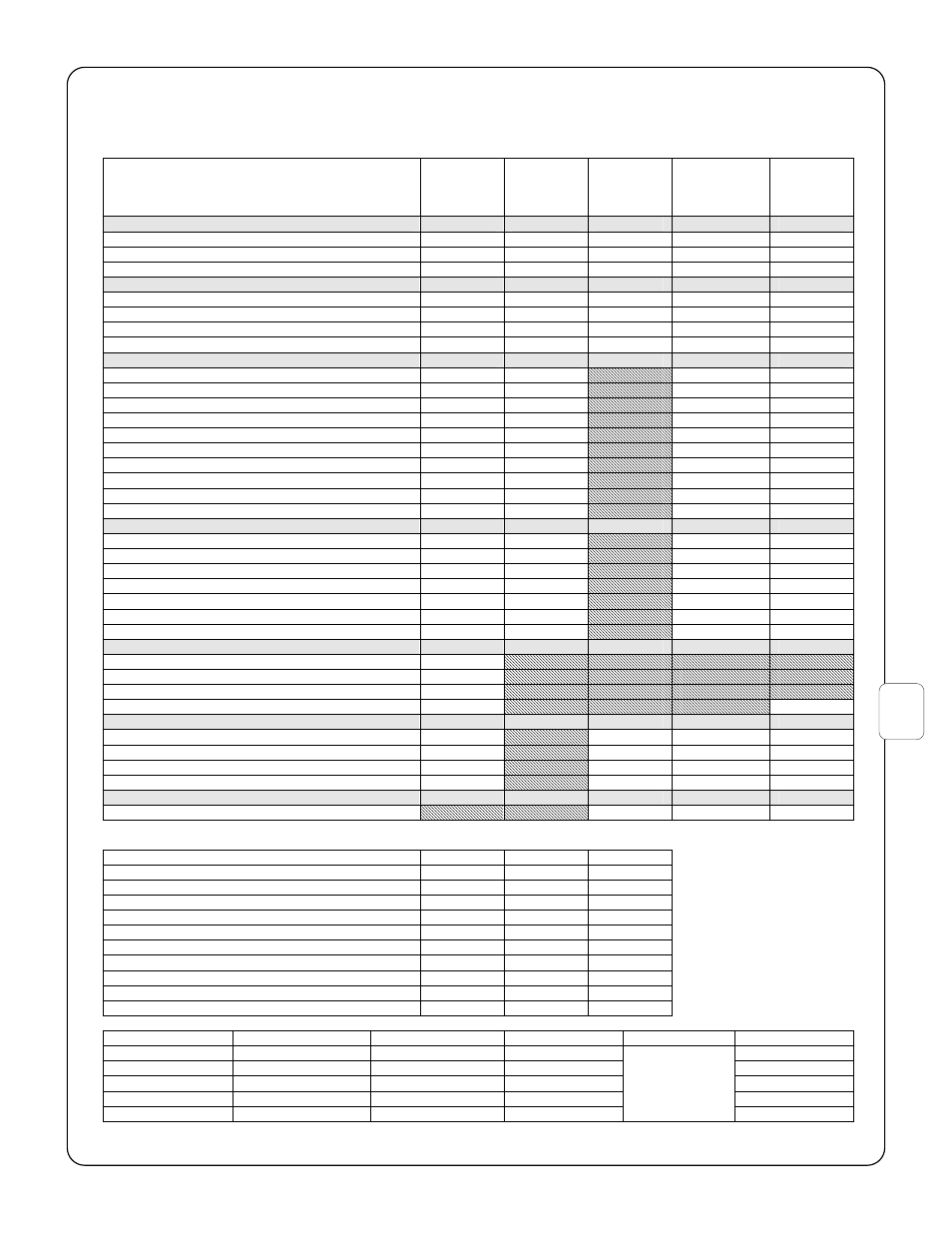
Appendix D. Battery Capacity Calculation
A
B
C
D
E
F
QUANTITY
OF
DEVICE/
MODULE
STANDBY
CURRENT
(Amps)
MAXIMUM
ALARM
CURRENT
(Amps)
TOTAL
STANDBY
CURRENT
(Amps)
TOTAL
ALARM
CURRENT
(Amps)
SYSTEM COMPONENTS
T1-MB and PDC
1
0.190
0.211
0.190
0.211
T2000-MBCLC and PDC
1
0.155
0.21
0.155
0.21
T8000-MBC and PDC
1
0.155
0.21
0.155
0.21
SERIAL DEVICES
T8000-LCU Addressable loop module
1
0.065
0.070
0.065
0.070
T8000-CM Conventional zone module
0.11
0.14
T8000-ANN/-RAN Remote annunciator
0.03
0.04
T8000-RC Two relay module
0.002
0.05
DETECTORS
ISpy IS800 58000-450 Heat detector
0.000 35
ISpy IS801 58000-550 Ion smoke detector
0.000 38
ISpy IS802 58000-650 Photo smoke detector
0.000 44
ISpy IS803 58000-886 Multi detector
0.000 47
55000-450 XP95A Heat detector
0.000 25
55000-550 XP95A Ion dmoke detector
0.000 28
55000-650 XP95A Photo smoke detector
0.000 34
55000-266 XP95A Beam detector
0.0165
55000-886 XP95A Multi detector
0.000 47
C-Spy, S60 and S65 Conventional (avg current)
0.0001
MODULES
ISpy IS810 55000-750 Short circuit isolator
0.000 12
ISpy IS811 55000-805 Switch monitor module
0.0006
ISpy IS812 55000-806 Priority switch monitor module
0.0006
ISpy IS813 55000-820 Switch monitor in/out module
0.000 85
ISpy IS814 55000-825 Sounder control module
0.001
ISpy IS816 55000-831 Mini switch monitor module
0.0006
ISpy IS815 55000-830 Mini priority switch mon mod
0.0006
Detectors and Modules LED ON current
A) Detectors and modules, total number
B) Estimated LED-ON number =(0.05 x A)
C) Alarm current LED = 0.0035 Amps
D) Total alarm LED ON current =(B x C)
NOTIFICATION APPLIANCES
Other –NAC #1, 3 Amps maximum
Other –NAC #2, 3 Amps maximum
Other –NAC #3, 3 Amps maximum
Other –NAC #4, 3 Amps maximum
Maximums are subject to total available
TOTAL CURRENT (Amps)
G
UNITS
FORMULA
RESULT
a) Standby current
Amps
a
b) Standby time (24 or 60 hours)
hours
b
c) Standby requirement (demand)
Ah
a x b
d) Alarm current
Amps
d
e) Alarm time (5 min = 0.0833, 10 min = 0.167)
hours
e
f) Alarm requirement (demand)
Ah
d x e
g) Battery backup capacity (supply)
Ah
c + f
h) Safety factor
Ah
g x 0.1
i) Minimum battery size required
Ah
g + h
REQUIRED BATTERY SIZE
Ah
Service
Standby Time
Alarm Time
Max Standby
Max Alarm
Max Battery Size
Local
24 hours
5 min
1.5A
40Ah
Central Station
24 hours
5 min
1.5A
40Ah
Proprietary
24 hours
5 min
1.5A
40Ah
Remote Station
60 hours
5 min
0.6A
40Ah
Auxiliary
60 hours
5 min
0.6A
7A for MBC
7A for MBCLC
4A for MB
40Ah