Co nt en ts, Example zone wiring on cm, Example slc wiring on lcu – Harrington Signal Tracker T8000 - Install Manual User Manual
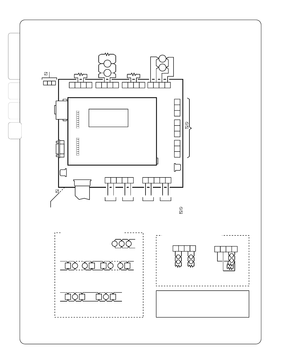
Page 24: Figure 3-2: wiring on mbc
Co
nt
en
ts
1
2
3
HSI #780-0867
FireSpy Tracker Installation Manual
20
290-0127
NOTES
:
1) Use only smoke detectors that are listed in compatibility listing in
owner's manual.
2) Leave end-of-line resistors on unused circuits.
3) All terminals are rated for 14-22 AWG wire unless otherwise noted.
4) Combined load of all devices, including indicating appliances, is not to
exceed 7A.
TYPICAL
STYLE B (CLASS B)
WIRING
4.7k
4.7k
A+
A-
B+
B-
ZONE
TYPICAL
STYLE D (CLASS A)
WIRING
TYPICAL
STYLE Y
(CLASS B)
WIRING
USB
PORT
ETHERNET
PORT
(OPTIONAL)
SERIAL
PORT
10K
LINE
NEU/LINE
EAR
TH
LINE INPUT
120VAC - 50/60Hz
230VAC - 50/60Hz
RS485
TO SERIAL
MODULES
TYPICAL STYLE Z
(CLASS A)
WIRING
(end-of-line resistor
not needed)
CONTACTS RATED
10A @ 30VDC
10A @ 250VAC
1.0 POWER FACTOR
USE ONLY POLARIZED
DEVICES ON NACs
Polarity shown is alarm condition
ALL NACs ARE REGULATED 24 DC
+
-
- +
24VDC
P1
RS485
B+
A+
A-
B-
B+
A+
A-
B-
P7
NAC
B+
A+
A-
B-
P8
NAC
B+
A+
A-
B-
NC
COM
NO
NC
COM
NO
NC
COM
NO
P9
NAC
P6
J3
J4
J2
P3
P4
P5
NAC
SUPV ALARM
TROUBLE
ALARM
24VDC
TO SERIAL
MODULES
BATTERY
CABLE
(TO P2)
RS485
TO SERIAL
MODULES
+
-
- +
24VDC
P2
RS485
24VDC
TO SERIAL
MODULES
+
+
+
+
10K
10K
P10
(U20)
MBC
J6
TO NETWORK
COMMUNICATOR
A+
A-
B+
B-
ZONE
Marks non-supervised circuits
Marks non-power-limited circuits
All others are supervised and power limited.
Segregate power-limited wiring from
non-power-limited wiring by at least 1/4 inch.
SUPERVISED AND POWER LIMITED
S
P
4.7k
4.7k
Example zone wiring on CM
S
P
P
P
TO RC
J1 jumpers present
TYPICAL STYLE 4 (CLASS B) WIRING
SLC B-
SLC B+
Example SLC wiring on LCU
Isolators (optional) separate each zone
TYPICAL STYLE 6 (CLASS A) WIRING
ZONE 1
SLC A-
SLC A+
SLC B-
SLC B+
SLC A-
SLC A+
SLC B-
SLC B+
ZONE 2
Isolators separate each detector
Remove J1 jumpers
Remove J1 jumpers
TYPICAL STYLE 7 (CLASS A) WIRING
SW2
1
8
(RESERVED)
SW1
1
8
ON/OFF
Figure 3-2: Wiring on MBC