Co nt en ts – Harrington Signal Tracker T8000 - Install Manual User Manual
Page 30
Co
nt
en
ts
1
2
3
HSI #780-0867
FireSpy Tracker Installation Manual
26
290-0148
Non-power limited
areas are shaded
Non-power limited
areas must be
segregated from
power limited areas
by at least 1/4 inch
-
+
+
-
SHD
RS485
P1
24VDC
-
+
+ -
RS485
P8
24VDC
A+
A-
B+
B-
P9
A+
A-
B+
B-
P10
DB9M
J2
B+
A+
A-
B-
B+
A+
A-
B-
P7
NAC
B+
A+
A-
B-
P8
NAC
B+
A+
A-
B-
NC
COM
NO
NC
COM
NO
NC
COM
NO
P9
NAC
P6
J3
P3
J1
P4
P5
NAC
SERIAL
SUPV
ALARM
TROUBLE
ALARM
NEU
HOT
EARTH
TB1
1 2 3 4 5 6 7 8
1 2 3 4 5 6 7 8
1 2 3 4 5 6 7
TB3
8765
4321
TB2
1 2 3 4 5 6 7 8
1 2 3 4 5 6 7
1
11
S1
SN2
SN1
1
11
1
11
10K
10K
HOT
E
AR
TH
NEU
MBC-LC
XFMR
25HAVE,
50HAVE,
or
100HAVE
UDACT
or
NCA
ZSC-2A
OR
ZSC-4B
ZSC-2A
or
ZSC-4B
T2000E-CAB
To HAVE NAC input
From NAC output
From
MCC-LC
P8
To UDACT / NCA
Speaker zones
LINE INPUT
120 VAC
50-60 Hz
Batteries:
24VDC
18Ah max
Max 50VDC
per circuit
This area is non-power
limited for phone line
connections (if using
UDACT)
Batteries:
24VDC
18Ah max
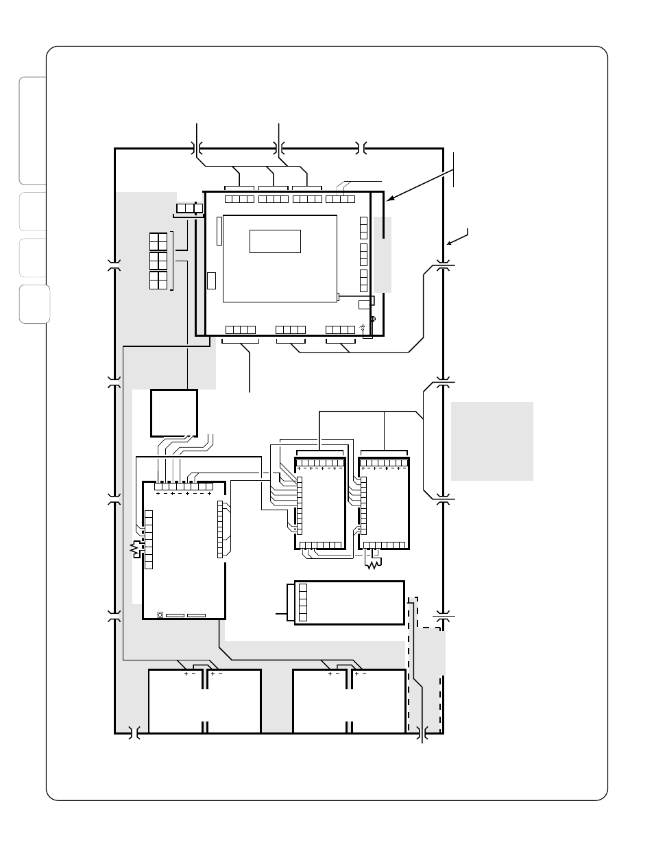
Figure 3-8: Wire routing on T2000E