Bryant 580F User Manual
Page 73
—
73
—
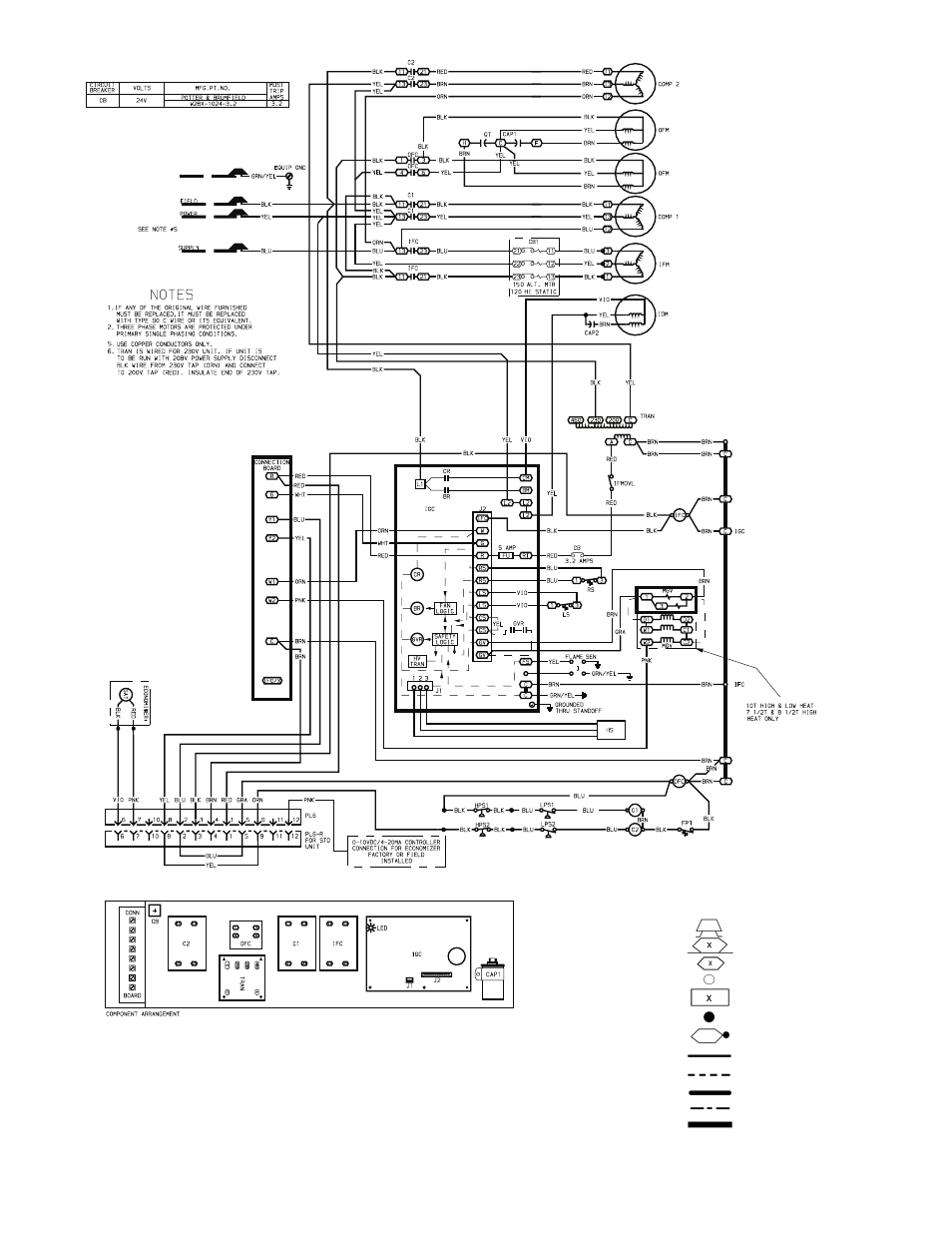
Fig. 52 — Typical Unit Wiring Schematic (208/230-3-60 Unit Shown)
IFM
—
Indoor Fan Motor
IFMOVL —
Indoor Fan Motor Overload Switch
IGC
—
Integrated Gas Unit Controller
LPS
—
Low-Pressure Switch
LS
—
Limit Switch
MGV
—
Main Gas Valve
OFC
—
Outdoor Fan Contactor
OFM
—
Outdoor Fan Motor
P
—
Plug
PL
—
Plug Assembly
QT
—
Quadruple Terminal
RS
—
Rollout Switch
SAT
—
Supply Air Temperature Sensor
SEN
—
Sensor
TRAN
—
Transformer
Field Splice
Marked Wire
Terminal (Marked)
Terminal (Unmarked)
Terminal Block
Splice
Splice (Marked)
Factory Wiring
Field Control Wiring
Field Power Wiring
Accessory or Optional Wiring
To indicate common potential only;
not to represent wiring.
LEGEND
C
—
Contactor, Compressor
CB
—
Circuit Breaker
COMP —
Compressor Motor
EQUIP —
Equipment
FPT
—
Freeze Up Protection Thermostat
GND
—
Ground
HPS
—
High-Pressure Switch
HS
—
Hall-Effect Sensor
I
—
Ignitor
IDM
—
Induced-Draft Motor
IFC
—
Indoor Fan Contactor