Table 32 — economi$er+ inputs and outputs, Table 33 — start-up mode sequence – Bryant 580F User Manual
Page 54
—
54
—
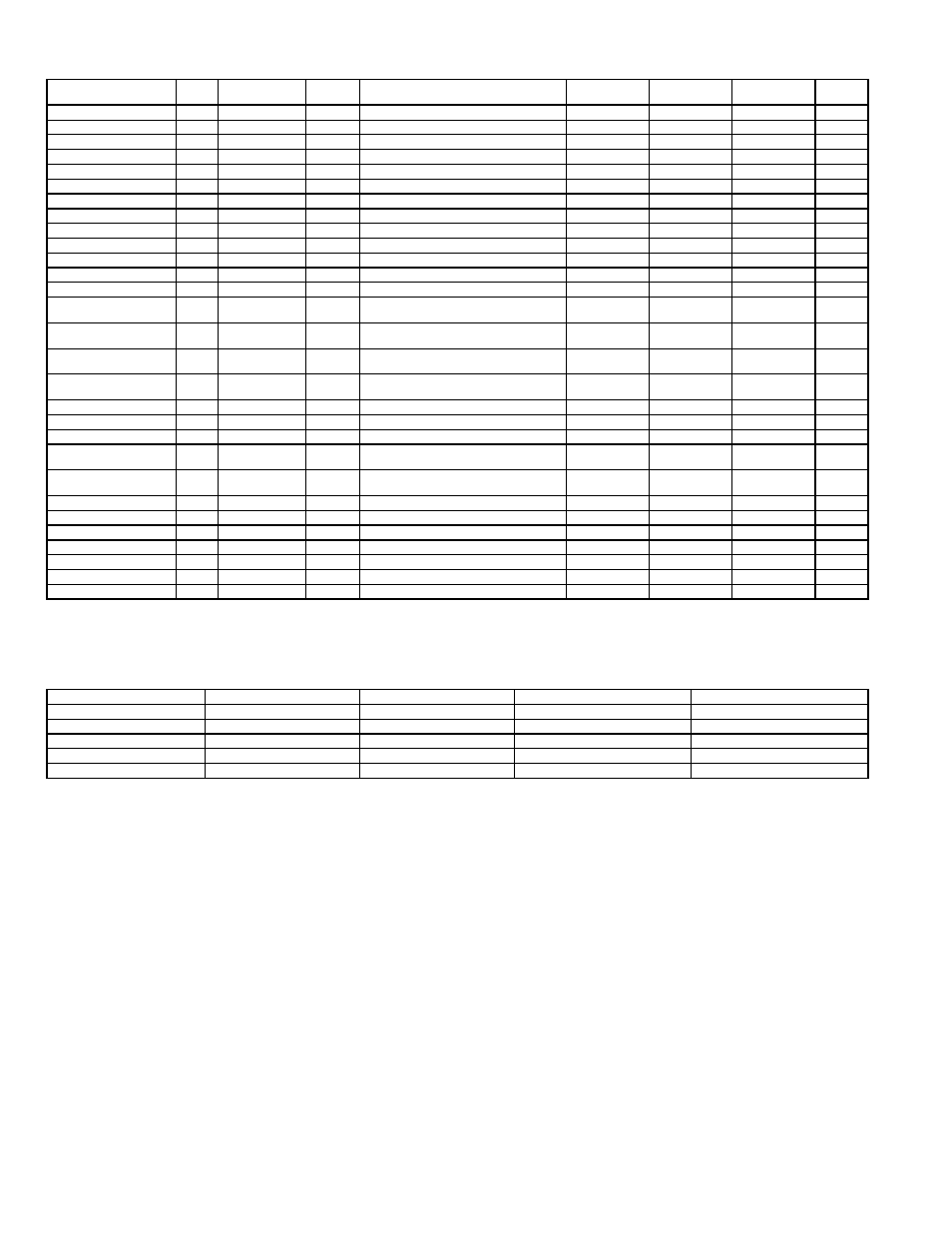
Table 32 — EconoMi$er+ Inputs and Outputs
*If there are 3 stages then there can only be 1 stage of power exhaust.
†If there are 4 stages then there will not be power exhaust stages that will be directly controlled.
Table 33 — Start-Up Mode Sequence
LED — Light-Emitting Diode
INPUT
NAME
TYPE
USE
INPUT/OUTPUT
RANGE
CONVERSION
RANGE
CONVERSION
RESOLUTION
CONNECTION
PIN NO.
THERMOSTAT INPUTS
Y1 (Cool/Low Cool)
Y1
Switch
Standard
18-30 vac 50/60 Hz w/min 24 mA Load
NA
On/Off
J1
1
Y2 (Cool 2/High Cool)
Y2
Switch
Option
18-30 vac 50/60 Hz w/min 24 mA Load
NA
On/Off
J1
2
G (fan)
G
Switch
Standard
18-30 vac 50/60 Hz w/min 24 mA Load
NA
On/Off
J1
3
Occupied/Unoccupied
OCC
Switch
Option
18-30 vac 50/60 Hz w/min 24 mA Load
NA
On/Off
J1
4,5
POWER
Power
24V
Input
Standard
18-30 VAC 50/60 Hz
NA
NA
J2
1,2
ECONOMIZER MOTOR
Control
CNT
2-10 vdc
Standard
2-10 vdc
0-100%
1%
J2
3,4,5
ANALOG INPUTS
Supply Air Temperature
SAT
10 K Thermistor
Standard
1816 to 86407 Ohms
30 to 125 F
0.8 F
J3
1,2
Outside Air Temperature
OAT
10 K Thermistor
Standard
1816 to 86407 Ohms
30 to 125 F
0.8 F
J3
3,4
Return Air Temperature
RAT
10 K Thermistor
Option
1816 to 86407 Ohms
30 to 125 F
0.8 F
J3
5,6
Indoor Humidity
IRH
4-20 mA,
Loop Powered
Option
4-20 mA, 24 vdc
0-100%
.08 mA
J3
7,8,9
Outdoor Humidity
ORH
4-20 mA,
Loop Powered
Option
4-20 mA, 24 vdc
0-100%
.08 mA
J3
10,11,12
Indoor CO
2
IAQ
4-20 mA,
Ext Sourced
Option
4-20 mA, 24 vdc
0-200 PPM/10
10 PPM
J3
13,14
Remote Minimum
Position Pot
MIN
10K
Option
10K to 100K Ohms
0 to 100%
1%
J3
15,16,17
RELAY OUTPUTS
Cooling Stage 1
CP1
Relay
Standard
24 vac, 2.5 Amps at 24 vac
NA
On/Off
J4
1,3,4
Cooling Stage 2
CP2
Relay
Option
24 vac, 2.5 Amps at 24 vac
NA
On/Off
J4
2,3,4
Power Exhaust 2/
Cooling Stage 3*
CP3/
EX2
Relay
Option
24 vac, 2.5 Amps at 24 vac
NA
On/Off
J4
5,6
Power Exhaust 1/
Cooling Stage 4†
CP4/
EX1
Relay
Option
24 vac, 2.5 Amps at 24 vac
NA
On/Off
J4
5,7
DISPLAY
Setpoint Switch 1
SP1
Digital
Standard
Open/Closed
Logic
Open/Closed
On Board
NA
Setpoint Switch 2
SP2
Digital
Standard
Open/Closed
Logic
Open/Closed
On Board
NA
LED 1
DS1
LED Output
Standard
Red
Logic
On/Off
On Board
NA
LED 2
DS2
LED Output
Standard
Yellow
Logic
On/Off
On Board
NA
LED 3
DS3
LED Output
Standard
Green
Logic
On/Off
On Board
NA
LED 4
DS4
LED Output
Standard
Green
Logic
On/Off
On Board
NA
TIME
LED 1/DS1 (RED)
LED 2/DS2 (YELLOW)
LED 3/DS3 (GREEN)
LED 4/DS4 (GREEN)
0-1.0 SEC
OFF
OFF
OFF
OFF
1-1.5 SEC
FLASH ½ SEC
OFF
OFF
OFF
1.5-2.0 SEC
OFF
FLASH ½ SEC
OFF
OFF
2.0-2.5 SEC
OFF
OFF
FLASH ½ SEC
OFF
2.5-3.0 SEC
OFF
OFF
OFF
FLASH ½ SEC