Adjusting center of gravity (cg), Control centering, Settings for control horns – E-flite UMX Hyper Taxi BNF User Manual
Page 8
8
EN
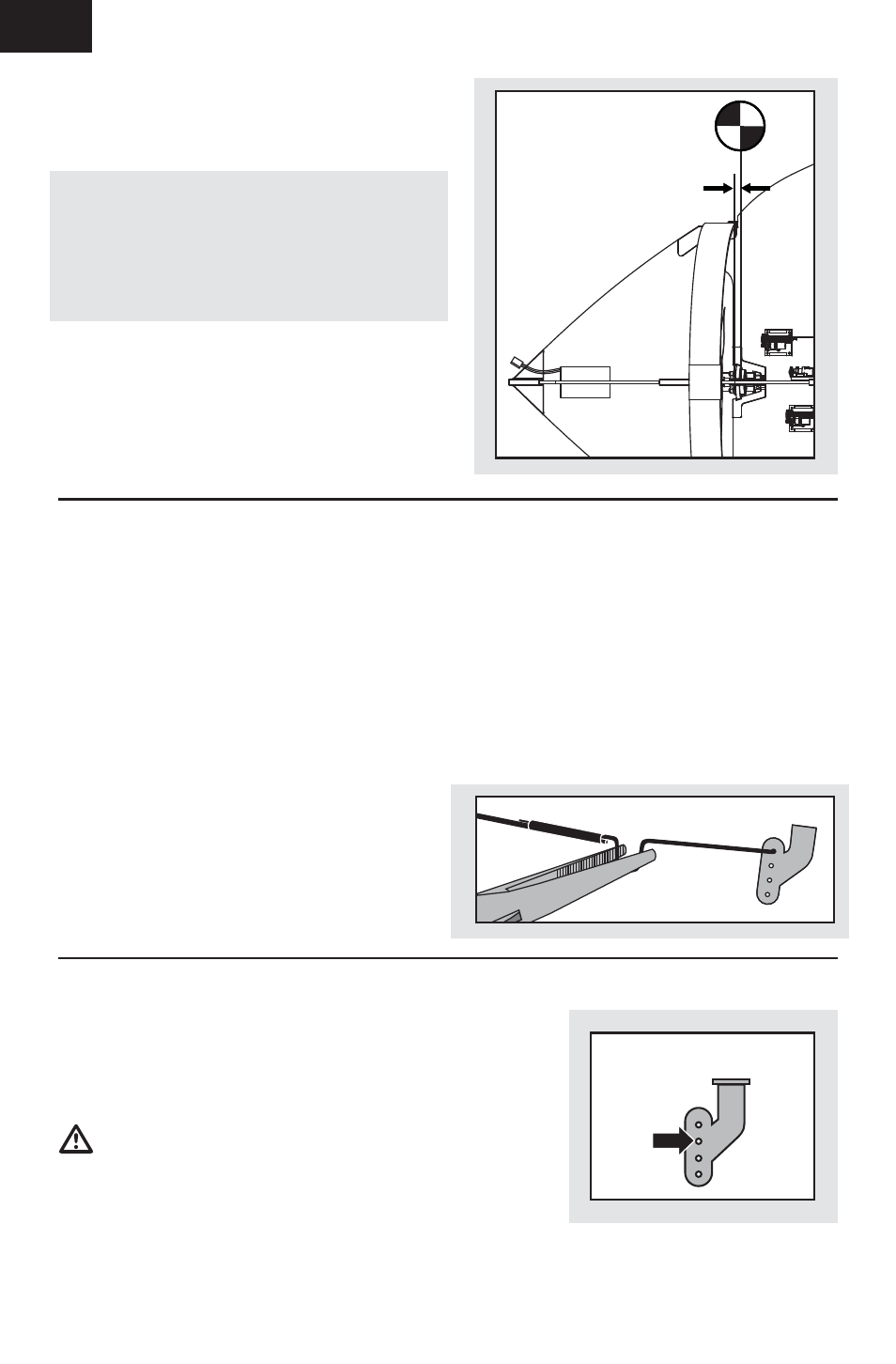
Adjusting Center of Gravity (CG)
2mm
The CG location is 2mm from the rear edge of the
propeller slot.
The battery slot is oversized to allow for Center of
Gravity adjustment. Start by placing the battery at
the front edge of the battery slot with the connector
plug facing the front of the aircraft. Adjust as
needed by sliding the battery back or forward. You
may also turn the battery pack 90 degrees, bringing
the plug to the side.
Control Centering
Before the fi rst fl ights, or in the event of an
accident, make sure the fl ight control surfaces
are centered. Adjust the linkages mechanically if
the control surfaces are not centered. Use of the
transmitter sub-trims may not correctly center the
aircraft control surfaces due to the mechanical
limits of linear servos.
1. Make sure the control surfaces are neutral
when the transmitter controls and trims are
centered. The transmitter sub-trim must be
always be set to zero.
2. When needed, use a pair of pliers to carefully
bend the metal linkage (see illustration).
3. Make the U-shape narrower to make the
connector shorter. Make the U-shape wider
to make the linkage longer.
Centering Controls After First Flights
For best performance with AS3X, it is important
that excessive trim is not used. If the model
requires excessive transmitter trim (4 or more clicks
of trim per channel), return the transmitter trim
to zero and adjust the linkages mechanically so
that the control surfaces are in the fl ight trimmed
position.
Settings for Control Horns
The following illustration shows the factory settings
for linkages on the control horns. After fl ying,
carefully adjust the linkage positions for the desired
control response.
CAUTION: Using settings other than the
factory settings, without proper experience, could
result in loss of control of your aircraft and a crash,
causing damage to the aircraft and personal injury.
All Control Surfaces