Lassic, Eries – Watts F1113-12RFP User Manual
Page 7
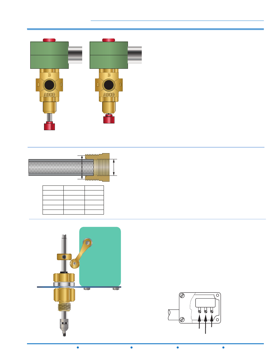
Globe
Angle
C
lassiC
s
eries
12541 Gulf Freeway
•
Houston, Texas 77034
•
(Ph) 713.943.0688
•
(Fx) 713.944.9445
•
www.watts.com
The valve Solenoid is prewired to the JB113 Junc-
tion Box and is equipped with a Manual Opera-
tor. Turning Manual Operator in (clockwise) ap-
proximatly 5-6 turns simulates electricity to the
Solenoid. Turning Manual Operator out (counter-
clockwise) returns the valve to electrical stand-by
service. Manual operator must be disengaged for
normal valve operation.
Disengaged
Engaged
A
B
C
Male Pipe
Female Pipe
Length
Thread (in)
Thread (in) Thread (in)
1/4
1/8
11/16
3/8
1/4
7/8
1/2
3/8
7/8
B
A
A
B
C
Male Pipe
Female Pipe
Length
Thread (in)
Thread (in) Thread (in)
1/4
1/8
11/16
3/8
1/4
7/8
1/2
3/8
7/8
B
A
A
The valve pilot circuit is equipped with a Model 60
Flo-Clean Strainer which is used to filter the fluid
passing through the control pilot circuit, and pro-
vide protection to pilot circuit speed controls and
pilots. It is installed in the inlet body port of the
main valve, exposing the strainer element to main
line flow. The currents and flow across the screen
create a self-scouring effect, cleaning the filter ele-
ment.
Single Pole Double Throw Switch
Common Lug
Normally Open
Normally Closed
The Model 51 Single Limit Switch provides local
visual and remote electrical indication of valve
position. The adjustable collar is set to contact the
trip arm when the main valve is closed. The collar
can be positioned on the stem by loosening the
set-screw to actuate the switch upon valve closure.
The single pole double throw Micro-Switch can be
connected to the building monitoring system to
indicate valve closure.
F113-12RFP (Globe)
F1113-12RFP (Angle)