Watts R48-20-3131100 User Manual
Page 11
F.
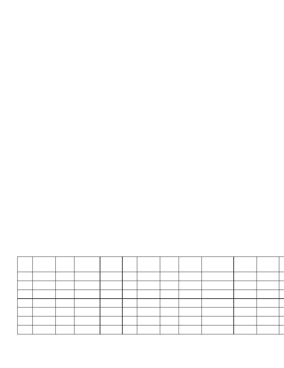
Operation and Maintenance Log
2. Verify that the controller on/off switch is in the off position.
3. Close the pump discharge completely then open it one turn. Note: All valves on this unit turn
clockwise to close.
4. Install four 20" five micron filter cartridges in the prefilter housing.
5. Open the reject control valve completely by turning it counterclockwise.
6. Close the reject recycle control valve completely by turning it counterclockwise.
7. Open the feed water shutoff valve installed in step III-B-1 above.
8. Engage the safety switch or disconnect (installed in step III-C-1 above) to apply electrical power to
the RO system.
9. Move the controller on/off switch to the on position. Move the switch back to the off position after
the pump starts and look at the motor fan as the pump stops to determine if the pump rotation is
correct. The fan should rotate in a counterclockwise direction when viewed from the top.
Continue with the startup if the pump is rotating in the proper direction. If the pump rotation is
backwards, reverse the rotation by shutting off the power and swapping any two of the three power
lines connected in step III.C.3 above
10. Turn the system on and allow the product and reject water to go to drain for 15 minutes.
11. Adjust the reject control valve, the reject recycle control valve and the pump discharge valve until
the desired flows are achieved. Closing the reject valve increases the recycle and product flow and
decreases the reject flow. Closing the reject recycle valve increases the reject and product flow and
decreases the recycle flow. Opening the pump discharge valve increases all of the flows. See the
temperature correction table in the appendix to determine the flow rates for different operating
temperatures.
12. Allow the product water to flow to drain for 30 minutes.
13. Turn off the system and connect the product line to the point of use. The product water line should
never be restricted. Membrane and/or system damage may occur if the product line is blocked.
14. Restart the system and record the initial operating data using the log sheet in the next section.
15. See the controller section for detailed information about the controller.
E. ELECTRONIC CONTROLLER – See separate booklet
DATE PRODUCT
GPM
REJECT
GPM
PUMP
DISCHARGE
PRESSURE
REJECT
PRESSURE
FEED
TDS
PPM
PRODUCT
TDS
PPM
FEED
WATER
TEMP
FEED
WATER
HARDNESS
FEED WATER
CHLORINE
LEVEL
PRE
FILTER
INLET
PRESSURE
PRE
FILTER
OUTLET
PRESSURE