Iv. replacement parts list v. membrane replacement, Ro system troubleshooting – Watts PWR4024 User Manual
Page 13
13
RO System Troubleshooting
PRoblem
coRRective action
General
high Product Water tds
Membrane expanded.
Replace membrane.
Membrane attack by chlorine
Carbon pre-filter may be exhausted. Replace with a new cartridge.
Clogged pre-filter-creates pressure drop and low reject flow.
Replace pre-filter cartridge.
Feed pressure too low.
Feed pressure must be at least 20psi.
Insufficiently flushed post-filter cartridge.
Flush post-filter with pure water.
Brine seal on membrane leaks.
Determine if seal or o-ring is bad. Replace as needed.
no Product Water or not enough Product Water
Feed water shut off.
Turn on feed water.
Low feed pressure. Feed pressure must be at least 20psi.
Consider booster pump.
Pre-filter cartridge clogged.
Replace pre-filter cartridge.
Membrane fouled.
Determine and correct cause; replace membrane.
Product check valve stuck.
Replace check valve fitting.
Low pump discharge pressure
Open pump discharge valve, replace pump
item
numbeR
descRiPtion
QuantitY PeR
sYstem
1
Pre filter housing 7 round 20"
1
2
Pressure Gauge, 2
1
⁄
2
", 0-100psi, LF
2
3
Pressure Gauge, 2
1
⁄
2
", 0-400psi, LF, Back Mount
1
4
Pressure Gauge, 2
1
⁄
2
", 0-400psi, LF, Bottom Mount
2
5
Flow Meter 1-30 gpm (product)
1
6
Flow Meter 1-17 gpm (reject)
1
7
Flow Meter 0.5 – 5 gpm (reject recycle)
1
8
Controller with conductivity meter
1
9
Enclosure with contactor and overload
10
Pump & Motor, 3-Phase, 60Hz, 10 hp
1
11
Low-pressure Switch
1
12
Inlet Solenoid Valve 24 volt
1
13
Watts Brand 4 x 40 RO Membranes
16
IV. Replacement Parts List
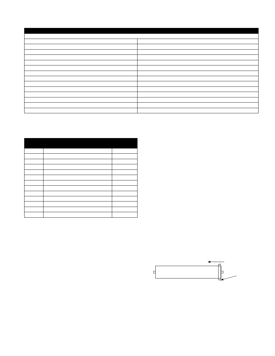
V. Membrane Replacement
1. Turn off the system and close the feed water shutoff valve.
2. Disconnect the membrane feed hoses by loosing the brass fit-
tings between the end of the hoses and the pressure vessel end
caps.
3. Remove the retaining rings from the pressure vessels.
4. Push the old membrane out of the vessel in the direction of the
feed flow.
5. Record the serial numbers of the new membranes.
6. Lightly lubricate the brine seals on the new membranes with
clean water.
7. I nstall the new membranes in the direction of flow with the brine
seal end going in last.
Note: Be sure to install an interconnector between the mem-
branes in each pressure vessel.
8. Lightly lubricate the end cap internal and external o-rings with
glycerin.
9. Install the end caps and secure them with the retaining rings.
10. Install the membrane feed hoses.
11. Verify that all retaining rings are installed.
12. Follow the start up procedure in section III-D.
Brine
Seal
Flow Direction
Membrane