Servicing the relief valve, Servicing first & second check valves, 3" (8 – 80mm) – Watts LFU009 User Manual
Page 3: Notice
3
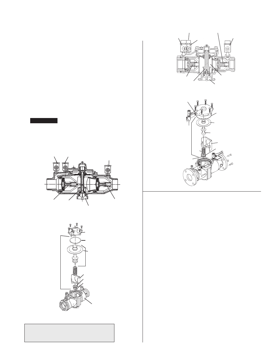
Servicing the Relief Valve
Series 009 and LF009
1
⁄
4
" – 3" (8 – 80mm)
1. Remove the four or six relief valve cover bolts while holding the
cover down.
2. Lift the cover straight off. The stem and diaphragm assembly will
normally remain with the cover as it is removed. The relief valve
spring will be free inside the body at this point.
3. The relief valve seat is located at the bottom of the body bore,
and can be removed, if necessary, for cleaning. The disc can be
cleaned without disassembly of the relief valve module. If it is
determined that the relief valve diaphragm and/or disc should be
replaced, the relief valve module can be readily disassembled
without the use of special tools.
NOTE: The disc rubber is mold-
ed into the disc holder and is supplied as a disc holder assembly.
4. To reassemble the relief valve, press the seat firmly into place in
the body, center the spring on the seat, and insert the cover and
relief valve module as a unit straight into the bore. Press down
on the cover to assure proper alignment. Insert and tighten bolts.
NOTICE
If cover will not press flat against body, stem assembly is
crooked and damage can result. Realign stem and cover before
bolts are inserted.
NOTE: No special tools required to service Series 009 2
1
/
2
" – 3"
(65 – 80mm).
Cover
Cover O-ring
Diaphragm
Stem & Diaphragm
Assembly
Retainer
Seat
Seat O-ring
Body
Relief V
alve
Service Parts Kit
Test Cock No.3
Test Cock No.2
Test Cock No.4
First Check
Module
Assembly
Second
Check Module
Assembly
Relief Valve
Assembly
Water Outlet
Test Cock No. 2
Test Cock No. 3
Test Cock No. 4
Ball Type
Test Cocks
Second Check
Module Assembly
R.P. Zone
Water Outlet
Relief Valve
Assembly
First Check
Module Assembly
Cover O-ring
Diaphragm
Stem Assembly
Retainer
Seat
Seat O-ring
Relief V
alve Service
Parts Kit
Spring
Flow Tube O-ring
1. Remove the relief valve assembly as outlined on page 3.
2. Remove the retainer from the body bore. The check valve mod-
ules can now be removed from the valve by hand or with a
screwdriver.
NOTE: The seats and springs of the first and second check
modules are not in ter change able. The heavier spring and smaller
diameter seat belong with the first check module.
3. The check seats are attached to the cage with a bayonet type
locking arrangement. Holding the cage in one hand, push the
seat inward and rotate coun ter clock wise against the cage. The
seat, spring cage, spring and disc assembly are now individual
com po nents.
4. The disc assembly may now be cleaned and re as sem bled or,
depending on its condition, may be dis card ed and replaced with
a new assembly from the repair kit. O-rings should be cleaned or
replaced as necessary and lightly greased with the FDA
approved silicon grease. For more information refer to repair
parts price list PL-RP-BPD.
5. Reassemble the check valve modules. Check modules are
installed in the valve body with the seat facing the valve inlet. The
modules must be securely in place before the retainer can be
replaced. Replace relief valve assembly.
NOTE: No special tools required to service Series 009 2
1
⁄
2
" – 3"
(65 – 80mm)
Servicing First & Second
Check Valves
Series 009 and LF009
1
⁄
4
" – 3" (8 – 80mm)
For repair kits and parts, refer to our Backflow
Prevention Products Repair Kits & Service Parts
price list PL-RP-BPD found on
www.watts.com.